


Chapter VII Performance feature test
94
Solid-state power amplifier(recommended model: S41-20, etc.)
Power meter(recommended model: 2432, 2434, etc.)
Power sensor(recommended model: 23211, 71712, N9304, etc.)
Attenuator: two 50W/20dB Attenuators
N/BNCadapter: one
RF cable: two (120cm)
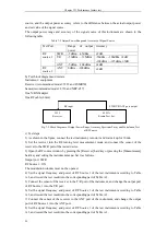
c) Test steps
1) As shown in the figure, start the instrument and warm it up for 30min.
2) Perform zero adjustment and calibration of the power meter and power sensor.
3) Measure the 20dBm signal at first. Directly connect the output of the signal source to the T/R
port of the tested device. Set the signal source as follows.
Frequency: 2MHz;
Power: 20 dBm
RF: ON
4) Open the RF meter window by pressing the [Measurement] hard key and setting the instrument
menu. Enable the RF power function, and set it as follows.
Display unit: dBm
Average: OFF
Compensation frequency of frequency response: 2MHz, corresponding to the output signal
frequency of the amplifier.
Read the RF power test result and record it in Table A.13.
5) Change the output signal frequency of the signal source into 50MHz, 800MHz and 1000MHz
according to the table, correspondingly change the frequency of the tested device, read the RF
power test result, and record it in Table A.13.
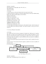
6) Test the 43dBm high-power signal. At first, calibrate the attenuation of the attenuator and cable
at 800MHz, connect the output of the signal source to the sensor of the power meter through the
test cable and attenuator group. Set the frequency factor of the power meter, and set the signal
source as follows.
Frequency: 800MHz;
Power: 0 dBm
RF: ON
Obtain the attenuation of P
800M
of the cable and attenuator group with the power meter (0-P). The
attenuation of P
1000M
at
1000MHz can also be obtained in the same method.
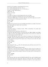
7) Obtain the set value of the signal source in the high-power output. Connect the output end of
the signal source to the input end of the amplifier, the output end of the amplifier to the attenuator
group, and the output end of the attenuator to the sensor of the power meter. Set the signal source
as follows.
Frequency: 800MHz;
Power: -30 dBm
RF: OFF
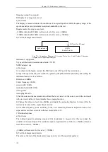
Set the frequency of the power meter as 800MHz. Enable the RF source, open the amplifier output,
observe the measured power, and adjust the output power of the signal source, until the displayed
value P of the power meter is 43dBm-P
800M
. Record the set value A
800M
of the signal source at
Summary of Contents for 4992A
Page 1: ...I 4992A Radio Test Set User Manual China Electronics Technology Instruments Co Ltd...
Page 2: ......
Page 5: ......
Page 6: ......
Page 7: ......
Page 23: ...Article I Handling Instructions 11 Article I Handling Instructions...
Page 93: ...81 Article II Technical Specifications...
Page 132: ...Article III Maintenance Instructions 120 Article III Maintenance Instructions...


