


Chapter 6 - Parameter Description
6-24
current signal value. For example, if current signal
from BMS is 4-20mA, I/O-09 should be set to
20mA. The default value is 20mA and can be
changed from 0 to 20mA.
I/O-10
should normally be set to 50Hz or 60Hz.
Do not set
it to any Frequency to be used as the
maximum speed limit because this changes the
speed reference control curve. The default value is
60Hz and can be changed from 0 to VFD
Maximum Frequency. (High limits should be
programmed on SET-14 or SET-28)
$ ) A 0+ '
" 2' !
$! '
!-
These parameters are available when SET-10 is set
to Pulse. They are used to scale and adjust the pulse
input parameters.
I/O-11
provides a selection for pulse type A or A+B
depending on the encoder type.
Do not use
B input
if A type is selected.
I/O-12
provides a noise filtering time adjustment.
I/O-13
should be set to a minimum pulse signal
frequency value. The default value is 0kHz and can
be changed from 0 to 10kHz.
I/O-14
should normally be set to 0Hz.
Do not set
it to any frequency to be used as the
minimum speed limit because this changes the
speed reference control curve.
The default value is 0Hz and can be changed from 0
to VFD maximum Frequency.
I/O-15
should be set to a maximum pulse signal
frequency value. The default value is 10kHz and
can be changed from 0 to 100kHz.
I/O-16
should normally be set to 50Hz or 60Hz.
Do not set
it to any Frequency to be used as
maximum speed limit because this changes the
speed reference control curve. The default value is
60Hz and can be changed from 0 to VFD
Maximum Frequency.
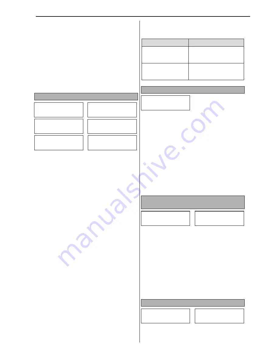
Pulse voltage high and low levels of Open
Collector Transistor output from Encoder
VFD Terminals
Pulse Level
A0 & B0
For
7.5-40HP
VFDs
High: (+) 3-
5
VDC
Low: (+) 0-2VDC
Max.Freq.: 100kHz
A0 & B0
For
50-700HP
VFDs
High: (+) 12-
15
VDC
Low: (+) 0-2.5VDC
Max.Freq.: 100kHz
$ ) 3+ %!
-
-!
1" "
The I/O-17 parameter has three selections: None,
Half of x1 and Below x1.
None
- VFD does not monitor an analog signal loss.
Half x1
- VFD monitors the minimum analog signal
value and if it decreases below 0.5x[I/O-02] or
0.5x[I/O-07], the VFD will act based on I/O-18
selection.
Below x1
- VFD monitors the minimum analog
signal value and if it decreases below [I/O-02] or
[I/O-07], the VFD will act based on I/O-18
selection.
The VFD cannot determine a signal loss condition
if analog minimum value is set to 0.
$ ) 46 5+
" ! !
- -!
!
The
I/O-18
parameter has four selections: Hold,
Decel, Coast, and Protection
Hold
- VFD will run at previous speed at analog
signal loss condition.
Decel
- VFD will decelerate to 0Hz based on Decel
Time setting.
Coast
- VFD will stop producing output
immediately and motor will coast to stop.
Protection
- VFD will trip on Loss of Command.
I/O-19
determines the delay time for Analog Signal
Loss detection.
$ ) *A 3+
-
" -"
8 $! '
>
The VFD digital inputs M1~M8 are universal and
have identical programming selections. Each input
has a unique default setting but it can be changed to
I/O P Pulse x2
15 10.0 kHz
I/O P Pulse Set
11 A+B
I/O P Filter
12 10 ms
I/O P Pulse x1
13 0.0 kHz
I/O P Freq y1
14 0.00 Hz
I/O I Freq y2
16 60.00 Hz
I/O Wire Broken
17 half of x1
I/O Lost Command
18 Coast
I/O Time Out
19 1.0 sec
I/O M1 Define
20 Speed-L
I/O M8 Define
27 RX
Summary of Contents for CI-007-P2
Page 23: ......
Page 107: ......
Page 110: ...Chapter 6 Parameter Description 7 4 PID control with Pipe Broken function diagram...
Page 111: ...Chapter 6 Parameter Description 7 4 7 5 PID control with Pre PID function diagram...
Page 112: ...Chapter 6 Parameter Description 7 5 7 6 PID Control Setting Notes...
Page 113: ......


