


Chapter 5 – Parameter List
4-6
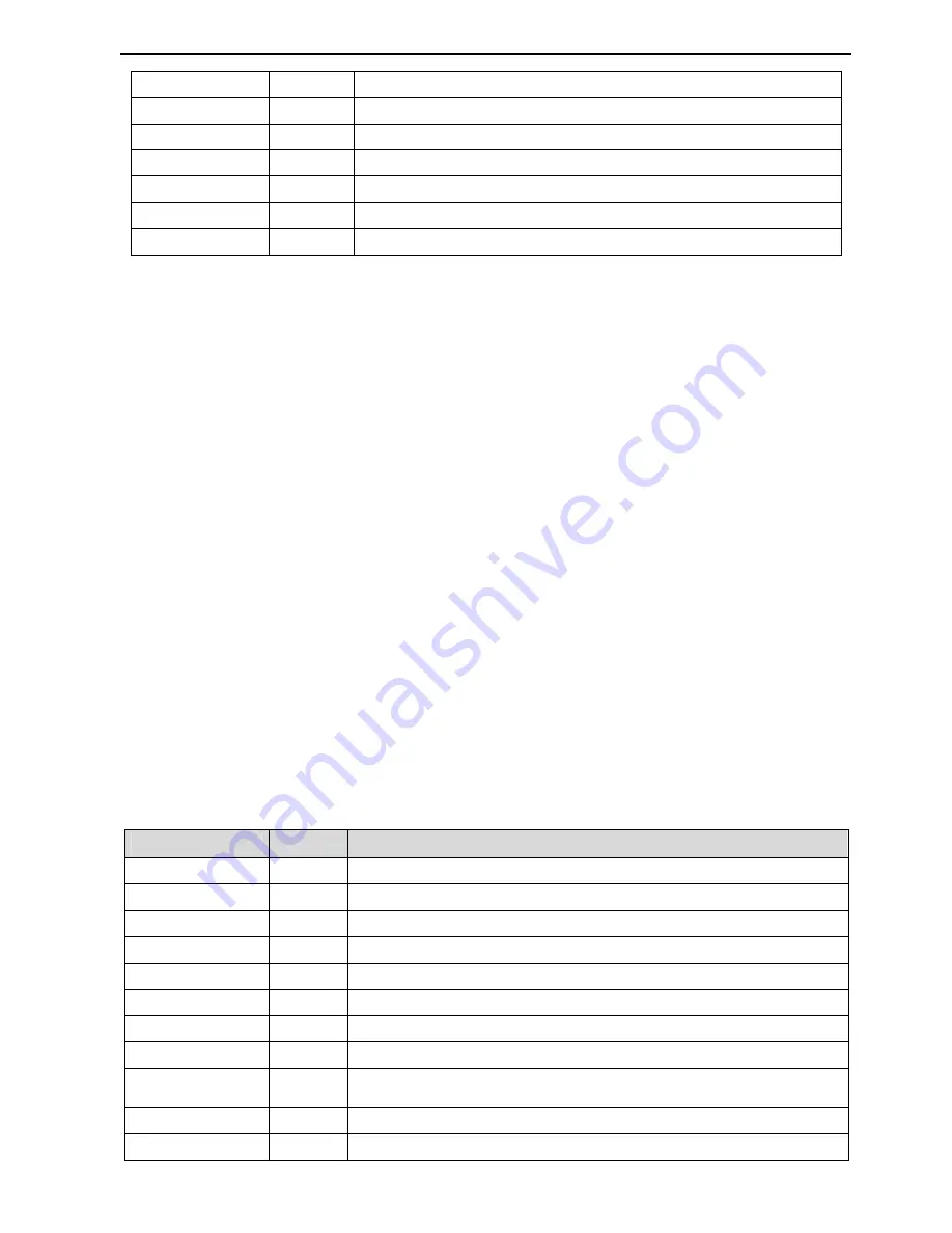
F/B Unit Max.
SET-25
Maximum Sensor Rating (Pumps 100PSI and fans 1inWC )
PID SetPoint
SET-26
PID control Set-point (50% of the sensor rating)
Local RemKey
SET-90
Local/Remote Mode Function (Cntl&RefStop)
Line Freq.
FG1-29
Power Line Frequency (60Hz)
Max. Freq.
FG1-30
VFD Maximum Output Frequency (60Hz)
Base Freq.
FG1-31
VFD provides full output voltage at this frequency (60Hz)
Rated Slip
FG2-42
Motor Slip= [SET-04]- [Motor Nameplate RPM] (50RPM)
* Note: The synchronous speed is a speed of the motor winding magnetic field without slip. Round the motor
nameplate RPM to determine this speed. Example: 1750RPM is 1800RPM Synch. and 3450RPM is 3600RPM
Synch.
4.3.2 V/F (Voltage/Frequency) control mode
The control mode parameter FG2-60 is set to V/F mode by default, which changes output voltage
corresponding to output frequency based on V/F pattern selected in parameter FG1-40. This mode uses
standard industrial motor parameters for internal calculations and provides stable and reliable control for
most of the motors in HVAC and pump applications.
4.3.3 Slip Compensation control mode
The control mode parameter FG2-60 should be set to Slip Comp. This mode is mostly used in heavy load
applications when the constant speed is required. The motor usually deceases speed when load on the shaft
increases. The VFD monitors a motor current, calculates approximate speed drop and compensates it by
increasing a speed reference in a range of motor slip set in parameter FG2-42. This control provides a
constant motor speed regardless of the load change.
4.3.4 Sensorless control mode
Set FG2-60 to Sensorless to enable Sensorless vector control. The Sensorless control mode provides better
torque control at low speeds, load fluctuation compensation, and better response on rapid load changes. It is
required to perform Auto tuning before starting Sensorless control in order to provide a stable motor control
in this mode. The Auto-Tuning operation does not turn a motor shaft and can be performed without
disconnecting a load from the motor. During Auto-tuning, the VFD sends different types of pulses to a
motor winding and calculates required motor parameters. Then it stores these parameters in the memory and
uses them for calculations to provide more precise control for the motor. It is recommended to use this mode
instead of V/F if motor draws higher than FLA current at full speed with nominal load or speed control at
higher speeds is unstable. The no-load motor current parameter FG2-44 and Inertia Rate FG2-46 are used in
Sensorless control calculations and should be set manually.
4.3.5 Monitoring VFD and Motor status
Parameter Name
Code
Description (Unit)
Current
DRV-17
VFD output current (A)
Speed
DRV-18
Motor speed (RPM)
DC link
DRV-19
DC bus voltage (V)
User Disp
DRV-20 VFD output voltage or power selected in FG2-81 (V or kW)
Fault
DRV-21
VFD Current fault.
TAR / OUT
DRV-22
VFD
T
arget and
O
utput frequency (Hz)
R/F
DRV-23
PID
R
eference and
F
eedback (Unit selected in SET-22)
R/F/T/O
DRV-25
PID
R
eference and
F
eedback (%),
T
arget/
O
utput Frequency (Hz)
V1/V2/V1S/I
DRV-26
The Number next to V or I input approximately has 0-4000 range.
V/400=Volts, I/200=mA. It is useful for analog signal troubleshooting.
Kilowatt-hour
FG1-54
kW/h reading. Can be monitored via communication.
Inv. Temp
FG1-55
Power Module Temperature (
°
C)
Summary of Contents for CI-007-P2
Page 23: ......
Page 107: ......
Page 110: ...Chapter 6 Parameter Description 7 4 PID control with Pipe Broken function diagram...
Page 111: ...Chapter 6 Parameter Description 7 4 7 5 PID control with Pre PID function diagram...
Page 112: ...Chapter 6 Parameter Description 7 5 7 6 PID Control Setting Notes...
Page 113: ......


