21
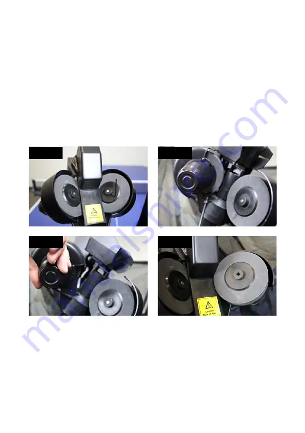
For the upper motors, the procedure is a little bit different. Begin by removing the 4 mm hex adjustment
screw (see Photo 9B). Grab a hold of the motor cover, and pivot the entire motor mechanism away from
the Ball Tube (see Photos 9C & 9D). Now you can remove the old wheel and push the new wheel on the
motor shaft, and then refasten the wheel onto the motor shaft using the same procedures as described
above for the lower wheel, then replace and tighten the 4 mm hex screw.
These upper wheels may not be as easy to remove from the shaft, or put back on the shaft, due to the
close proximity of the Head Panel and the Oscillation & Trajectory Motor Cover. But because the wheels
are foam, the wheel can be removed and replaced with a little force to bend the foam out of place. If
removing the wheel is too difficult, you can remove the Oscillation & Trajectory Motor Cover to provide
more room for wheel removal and replacement.
Even if only one of the upper wheels has been damaged, we recommend replacing all upper wheels at
once, to ensure the robot does not become inaccurate After replacing wheels, adjust the wheel spacing
as described in the previous section, Checking and Adjusting Wheel Clearance.
Photo 9A
Photo 9B
Photo 9C
Photo 9D
Ball Jams
Your robot is equipped with a special system to detect and react to problems in the ball channel. When
the system detects a problem, it will attempt to automatically clear the ball jam by turning the Ball Feed
Motor and the wheels forward and backward 7-8 times.
If the error can’t be resolved so, all motors stop and the system shows an error code on the display (Er1
or Er2). Er1 indicates a problem in the base of the robot, and Er2 indicates a problem in the head of the
robot (see Troubleshooting, p. 22).


