6
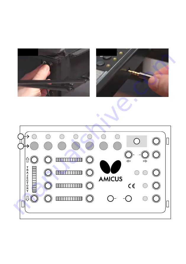
Connect the Control Panel Cable into the jack plug (looks like a headphone jack) on the side of the
Base (see Photo 6A). Pull the Control Panel Cable to the opposite side of the table and connect it to
the Control Panel (see Photo 6B). Next attach the Control Panel Bracket on the side of the table and
then hang the Control Panel on the bracket. You may use a Velcro strip to help secure the bracket
onto the side of the table. Before beginning to play on your robot, remove the rubber bands and blue
foam pad used on the head to help protect the Deflector Plate during shipment.
Photo 6A
Photo 6B
2. Control Panel
EXPERT
Start/Stop
Sample
Spin
Speed
Sidespin
Top
Back
Right
Left
Right
Left
High
Low
More
Less
-4 -3 -2 -1 0 1 2 3 4 5 6
1 3 5 7 9 11 13 15 17 19 21
9075 604530 0 30456075 90
-5 -4 -3 -2 -1 0 1 2 3 4 5
Placement
Cycle
Random
1
2
3
4
5
6
7
Place
Scatter
Step
MEMORY/CYCLE
Clear
Quit
Save
–
Ball
/
Min
+
AFC
5
4
3
2
1
0
-1
-2
-3
-4
-5
1
2
3
5
6
7
8
4
11
12
15
16
17
18
19
20
21
22
13
14
9
10
1
Ball LEDs (1–7)
— When lit and solid, indicates a Ball is programmed for that spot. A flashing
light Current Ball. Only selected balls can be changed. Number of lit LEDs indicates the num-
ber of balls in your Exercise.
2
Ball Buttons (1–7)
— When pressed, selects that ball. Once selected, all settings shown on


