


2003 Buell XB9R: Appendix B
B-1
HOME
73
AMP MULTILOCK ELECTRICAL CONNECTORS
B.1
REMOVING SOCKET/PIN
TERMINALS
1.
Remove connector from the retaining device, either
attachment or rosebud clip.
2.
Depress the button on the socket terminal side of the
connector (plug) and pull apart the pin and socket
halves.
3.
Bend back the latch slightly and free one side of second-
ary lock, then repeat the step to release the other side.
Rotate the secondary lock outward on hinge to access
terminals in chambers of connector housing.
4.
Looking in the terminal side of the connector (opposite
the secondary lock), take note of the cavity next to each
terminal.
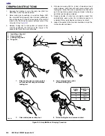
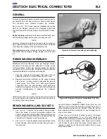
5.
See
Figure B-1.
With the flat edge against the terminal,
insert the pick tool (Snap-On TT600-3) into the cavity
until it stops. Pivot the end of the pick away from the ter-
minal (locktab is inside housing) and gently tug on wire to
pull terminal from chamber. Do not tug on the wire until
the tang is released or the terminal will be difficult to
remove. A “click” is heard if the tang is engaged but then
inadvertently released. Repeat the step without releasing
the tang.
NOTE
●
If pick tool is not available, a push pin/safety pin may be
used instead.
●
An ELECTRICAL TERMINAL CRIMP TOOL (Part No.
HD-41609) is used to install Amp Multi lock pin and
socket terminals on wires. If new terminals must be
installed, see Crimping Instructions on the next page.
INSTALLING SOCKET/PIN
TERMINALS
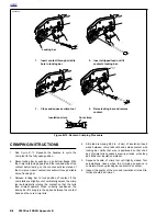
NOTE
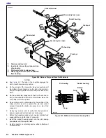
For wire location purposes, numbers are stamped into the
secondary locks of both the socket and pin housings. See
Figure B-2.
1.
From the secondary lock side of the connector, insert the
terminal into its respective numbered chamber until it
snaps in place. For proper fit, the slot in the terminal
must face the tang in the chamber.
Figure B-1. 10-Place Amp Multilock Connector
d0242x3x
Secondary lock open
Secondary lock open
Pin housing
Latch
Pin terminal
Socket housing
Secondary lock open
Socket terminal
Button
Latch
Latch
Summary of Contents for XB9R 2003
Page 2: ...1 2 Edit Me Printed June 5 2002 12 26 pm ...
Page 35: ...D 2 2003 Buell XB9R Appendix D HOME Figure D 2 Rear Brake Systems Top View b1115xbx ...
Page 36: ...2003 Buell XB9R Appendix D D 3 HOME Figure D 3 Rear Brake Systems Left Side View b1116xcx ...
Page 47: ...D 14 2003 Buell XB9R Appendix D HOME NOTES ...
Page 49: ......
Page 77: ...1 28 2003 Buell XB9R Maintenance HOME NOTES ...
Page 103: ...1 54 2003 Buell XB9R Maintenance HOME NOTES ...
Page 105: ... 2 ...
Page 191: ......
Page 263: ...3 72 2003 Buell XB9R Engine HOME NOTES ...
Page 299: ...4 2 2003 Buell XB9R Fuel System HOME NOTES ...
Page 385: ...4 88 2003 Buell XB9R Fuel System HOME NOTES ...
Page 421: ...4 124 2003 Buell XB9R Fuel System HOME NOTES ...
Page 423: ......
Page 445: ...5 22 2003 Buell XB9R Starter HOME NOTES ...
Page 447: ......
Page 469: ...6 22 2003 Buell XB9R Drive Transmission HOME NOTES ...
Page 497: ...6 50 2003 Buell XB9R Drive Transmission HOME NOTES ...
Page 499: ......