


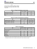
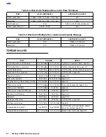


2003 Buell XB9R: Drive/Transmission
6-11
HOME
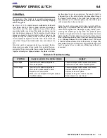
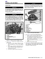
REMOVAL/DISASSEMBLY
Clutch Pack
1
1
WARNING
1
WARNING
To protect against shock and accidental start-up of vehi-
cle, disconnect the negative battery cable before pro-
ceeding. Inadequate safety precautions could result in
death or serious injury.
1.
Remove primary cover. See
6.2 PRIMARY CHAIN
.
1
1
WARNING
1
WARNING
Do not attempt to disassemble the clutch without
SPRING COMPRESSING TOOL (Part No. HD-38515-A),
CLUTCH SPRING FORCING SCREW (Part No. HD-38515-
91) and proper eye protection. Otherwise, the highly
compressed diaphragm spring could fly out with great
force which could result in death or serious injury.
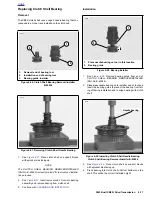
2.
See
Figure 6-13.
Attach tools to compress clutch dia-
phragm spring.
a. Thread the CLUTCH SPRING FORCING SCREW
(Part No. HD-38515-91) onto the clutch adjusting
screw.
b.
Place the bridge of SPRING COMPRESSING TOOL
(Part No. HD-38515-A) against diaphragm spring.
c.
Install bearing and washer.
d.
Thread the tool handle onto end of forcing screw.
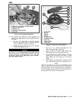
CAUTION
See
Figure 6-14.
Turn compressing tool handle only the
amount required to release spring seat and remove snap
ring. Excessive compression of diaphragm spring could
damage clutch pressure plate.
3.
See
Figure 6-14.
Remove pressure plate assembly.
a. Place a wrench on the clutch spring forcing screw
flats to prevent the forcing screw from turning.
b.
Turn compressing tool handle clockwise until tool
relieves pressure on retaining ring and spring seat.
Remove and discard retaining ring.
c. Unseat spring seat from the groove in clutch hub
prongs.
d.
Remove pressure plate assembly.
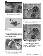
4.
See
Figure 6-12.
Remove the clutch pack from the hub/
shell assembly. The pack consists of seven fiber plates,
seven steel plates, one narrow fiber plate, one damper
spring and one damper spring seat.
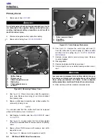
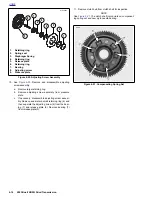
Figure 6-13. Compressing Clutch Diagram Spring
8807
1.
Tool handle
2.
Bridge
3.
Diaphragm spring
4.
Clutch spring forcing screw
5.
Bearing
6.
Washer
1
6
5
2
4
3
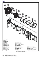
Figure 6-14. Pressure Plate Assembly
6250
1.
Tool handle
2.
Washer
3.
Bearing
4.
Bridge
5.
Forcing screw
6.
Diaphragm spring
7.
Snap ring
8.
Pressure plate
9.
Spring seat
1
3
2
9
8
7
4
6
5
Summary of Contents for XB9R 2003
Page 2: ...1 2 Edit Me Printed June 5 2002 12 26 pm ...
Page 35: ...D 2 2003 Buell XB9R Appendix D HOME Figure D 2 Rear Brake Systems Top View b1115xbx ...
Page 36: ...2003 Buell XB9R Appendix D D 3 HOME Figure D 3 Rear Brake Systems Left Side View b1116xcx ...
Page 47: ...D 14 2003 Buell XB9R Appendix D HOME NOTES ...
Page 49: ......
Page 77: ...1 28 2003 Buell XB9R Maintenance HOME NOTES ...
Page 103: ...1 54 2003 Buell XB9R Maintenance HOME NOTES ...
Page 105: ... 2 ...
Page 191: ......
Page 263: ...3 72 2003 Buell XB9R Engine HOME NOTES ...
Page 299: ...4 2 2003 Buell XB9R Fuel System HOME NOTES ...
Page 385: ...4 88 2003 Buell XB9R Fuel System HOME NOTES ...
Page 421: ...4 124 2003 Buell XB9R Fuel System HOME NOTES ...
Page 423: ......
Page 445: ...5 22 2003 Buell XB9R Starter HOME NOTES ...
Page 447: ......
Page 469: ...6 22 2003 Buell XB9R Drive Transmission HOME NOTES ...
Page 497: ...6 50 2003 Buell XB9R Drive Transmission HOME NOTES ...
Page 499: ......