


2003 Buell XB9R: Drive/Transmission
6-39
HOME
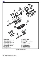
TRANSMISSION RIGHT CASE BEARINGS
6.10
REMOVAL
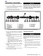
NOTE
See
Figure 6-69.
Refer to Transmission assembly right crank-
case half, for location of items discussed on this page.
1.
Remove transmission assembly. See
6.7 TRANSMIS-
SION DISASSEMBLY
.
2.
See
Figure 6-69.
Remove main drive 5th gear. Use
MAIN
DRIVE GEAR REMOVER AND INSTALLER (Part No.
HD-35316A). See
6.9 MAIN DRIVE GEAR
.
3.
At outside of case remove seal next to 5th gear bearing
retainer. Remove retaining ring.
4.
From inside transmission case drive bearings (5th gear,
countershaft or shifter shaft) out of bores. Carefully tap
bearings free by working around bearing diameter to
keep bearing from skewing.
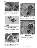
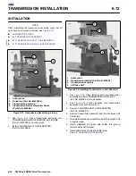
INSTALLATION
Mainshaft 5th Gear Ball Bearing
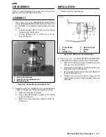
1.
See
Figure 6-70.
Locate MAIN DRIVE GEAR REMOVER
AND INSTALLER (Part No. HD-35316-A). Place cross-
plate pins in appropriate holes in transmission case.
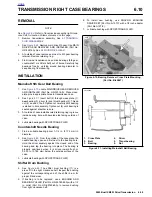
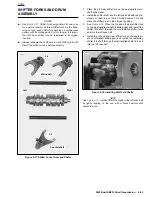
2.
See
Figure 6-71.
Insert bolt (2) through cross plate (1),
new bearing (3), driver (4) and thrust bearing (5). Thread
nut (6) on end of bolt. Tighten nut carefully until bearing
is started in bore squarely. Tighten nut (6) until bearing is
seated against shoulder in bore.
3.
At outside of case install beveled retaining ring in groove
inside bearing bore with beveled side facing outside of
case.
4.
Lubricate bearing with SPORT-TRANS FLUID.
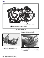
Countershaft Needle Bearing
1.
Find a suitable bearing driver 1-1/4 in. (31.75 mm) in
diameter.
2.
See
Figure 6-69.
From the outside of the case place the
needle bearing open end first next to the bearing bore.
Hold the driver squarely against the closed end of the
bearing and tap the bearing into place. The bearing is
properly positioned when it is driven inward flush or
0.030 in. (0.762 mm) below the outside surface of the
case.
3.
Lubricate bearing with SPORT-TRANS FLUID.
Shifter Drum Bushing
4.
See
Figure 6-69.
The shifter drum bushing (11) is a
press fit in the right crankcase half. Inspect the bushing
against the corresponding end of the shifter drum for
proper fit and wear.
5.
If bushing is to be replaced, use a BUSHING AND
BEARING PULLER (Part No. HD-95760-69A) with a 1/2
in. collet (Part No. HD-95765-69A) to remove bushing
from right crankcase half.
6.
To install new bushing, use SNAP-ON BUSHING
DRIVER SET (Part No. A-157C) with a 1/2 inch adapter
(Part No. A157-8).
7.
Lubricate bushing with SPORT-TRANS FLUID.
Figure 6-70. Bearing Remover Cross Plate Mounting
(Part No. B-45847)
Figure 6-71. Installing Mainshaft Ball Bearing
8681
1.
Cross Plate
2.
Bolt
3.
Bearing
4.
Driver
5.
Thrust bearing
6.
Nut
a0125xSX
Summary of Contents for XB9R 2003
Page 2: ...1 2 Edit Me Printed June 5 2002 12 26 pm ...
Page 35: ...D 2 2003 Buell XB9R Appendix D HOME Figure D 2 Rear Brake Systems Top View b1115xbx ...
Page 36: ...2003 Buell XB9R Appendix D D 3 HOME Figure D 3 Rear Brake Systems Left Side View b1116xcx ...
Page 47: ...D 14 2003 Buell XB9R Appendix D HOME NOTES ...
Page 49: ......
Page 77: ...1 28 2003 Buell XB9R Maintenance HOME NOTES ...
Page 103: ...1 54 2003 Buell XB9R Maintenance HOME NOTES ...
Page 105: ... 2 ...
Page 191: ......
Page 263: ...3 72 2003 Buell XB9R Engine HOME NOTES ...
Page 299: ...4 2 2003 Buell XB9R Fuel System HOME NOTES ...
Page 385: ...4 88 2003 Buell XB9R Fuel System HOME NOTES ...
Page 421: ...4 124 2003 Buell XB9R Fuel System HOME NOTES ...
Page 423: ......
Page 445: ...5 22 2003 Buell XB9R Starter HOME NOTES ...
Page 447: ......
Page 469: ...6 22 2003 Buell XB9R Drive Transmission HOME NOTES ...
Page 497: ...6 50 2003 Buell XB9R Drive Transmission HOME NOTES ...
Page 499: ......