


2003 Buell XB9R: Chassis
2-55
HOME
REAR SHOCK ABSORBER
2.22
GENERAL
The rear suspension is controlled by the shock absorber. The
XB9R shock allows adjustment of rear compression and
rebound damping and spring preload.
The most important rear shock adjustment is the preload set-
ting. Before making any damping adjustments, set the proper
preload. See
1.11 SUSPENSION DAMPING ADJUST-
MENTS
.
NOTE
The rear shock absorber contains no user serviceable parts.
REMOVAL
1.
Remove seat. See
2.38 SEAT
.
1
1
WARNING
1
WARNING
Always disconnect the negative battery cable first. If the
positive cable should contact ground with the negative
cable installed, the resulting sparks may cause a battery
explosion which could result in death or serious injury.
2.
Disconnect and remove battery. See
1.4 BATTERY
MAINTENANCE.
3.
Remove tail body work. See
2.36 TAIL FRAME AND
BODY WORK
.
4.
Place a scissor jack under jacking point and raise rear
wheel off ground. For location of jacking point see
Figure
2-98.
5.
See
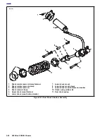
Figure 2-85.
Remove upper shock (5) and lower
shock mount fasteners (6 and 9) and lower shock mount
sleeve (8).
6.
Remove rear shock reservoir clamp (2).
7.
See
Figure 2-84.
Cut cable strap.
8.
Feed rear shock reservoir through tail section.
9.
Remove rear shock.
a. Raise motorcycle up approximately 2 more inches
(51 mm).
b.
Remove shock through the top of the tail section
(opening underneath rider seat).
INSTALLATION
1.
See
Figure 2-85.
Install upper shock mount and tighten
fastener (5) to 49-51 ft-lbs (66-69 Nm).
2.
Install lower shock mount with fasteners (6, 9) and lower
shock mount sleeve (8) and tighten to 15-17 ft-lbs (20.3-
23 Nm).
3.
Feed rear shock reservoir through tail section.
D.1 HOSE
AND WIRE ROUTING
for correct routing.
a.
Loosely install reservoir in clamp.
b.
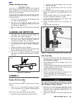
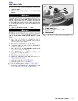
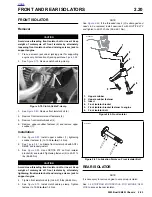
See Figure 2-83. Temporarily place upper body work
onto tail section and adjust reservoir placement so
dial aligns with bodywork.
c.
Tighten clamp on reservoir to 96-120 in-lbs
(11-14 Nm).
4.
See
Figure 2-84.
Add cable strap.
NOTE
Verify compression dial is facing up. See
Figure 2-85.
5.
Install upper body work. See
2.36 TAIL FRAME AND
BODY WORK
.
1
1
WARNING
1
WARNING
Always connect the positive battery cable first. If the pos-
itive cable should contact ground with the negative cable
installed, the resulting sparks may cause a battery explo-
sion which could result in death or serious injury.
6.
Install battery by threading positive cable (red) into
threaded hole first tightening to 72-96 in-lbs (8-11 Nm).
See
1.4 BATTERY MAINTENANCE.
7.
Install seat. See
2.38 SEAT
.
Figure 2-83. Adjuster Screw Alignment
Figure 2-84. Cable Strap
1.
Adjuster screw
2.
Adjuster screw alignment hole
1
8354
2
8463
Summary of Contents for XB9R 2003
Page 2: ...1 2 Edit Me Printed June 5 2002 12 26 pm ...
Page 35: ...D 2 2003 Buell XB9R Appendix D HOME Figure D 2 Rear Brake Systems Top View b1115xbx ...
Page 36: ...2003 Buell XB9R Appendix D D 3 HOME Figure D 3 Rear Brake Systems Left Side View b1116xcx ...
Page 47: ...D 14 2003 Buell XB9R Appendix D HOME NOTES ...
Page 49: ......
Page 77: ...1 28 2003 Buell XB9R Maintenance HOME NOTES ...
Page 103: ...1 54 2003 Buell XB9R Maintenance HOME NOTES ...
Page 105: ... 2 ...
Page 191: ......
Page 263: ...3 72 2003 Buell XB9R Engine HOME NOTES ...
Page 299: ...4 2 2003 Buell XB9R Fuel System HOME NOTES ...
Page 385: ...4 88 2003 Buell XB9R Fuel System HOME NOTES ...
Page 421: ...4 124 2003 Buell XB9R Fuel System HOME NOTES ...
Page 423: ......
Page 445: ...5 22 2003 Buell XB9R Starter HOME NOTES ...
Page 447: ......
Page 469: ...6 22 2003 Buell XB9R Drive Transmission HOME NOTES ...
Page 497: ...6 50 2003 Buell XB9R Drive Transmission HOME NOTES ...
Page 499: ......