


2003 Buell XB9R: Drive/Transmission
6-49
HOME
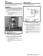
7.
See
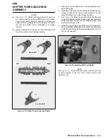
Figure 6-91.
Scribe a line on the transmission
sprocket nut and continue the line on the transmission
sprocket as shown.
8.
Tighten the transmission sprocket nut an additional 30°-
40°.
9.
See
Figure 6-89.
Install lockplate over nut so that two of
lockplate’s four drilled holes (diagonally opposite) align
with sprocket’s two tapped holes.
NOTE
The lockplate has four screw holes and can be turned to
either side, so you should be able to find a position without
having to additionally tighten the nut. If you cannot align the
screw holes properly, the nut may be additionally TIGHT-
ENED until the screw holes line up, but do not exceed 45°.
NEVER LOOSEN nut to align the screw holes.
CAUTION
Maximum allowable tightening of sprocket nut is 45° of
counterclockwise rotation, after initially tightening to 50
ft-lbs. Do not loosen sprocket nut while attempting to
align the screw holes. If you cannot align lockplate and
sprocket screw holes, nut may be additionally tightened
45° as specified above. Tightening too much or too little
may cause the nut to come loose during vehicle opera-
tion.If you cannot align lockplate and sprocket screw
holes, nut may be additionally tightened until screw
holes align.
10. See
Figure 6-89.
Install two socket head screws through
aligned holes of lockplate and into tapped holes of
sprocket. Tighten to 90-110 in-lbs (10.2-12.4 Nm).
NOTE
The original equipment socket head screws (1) have thread-
locking compound applied to them. Since this compound
remains effective for about three removal/installation cycles,
the original screws may be reused up to three times. After the
third removal/installation cycle, replace both screws with new
screws identical to the original.
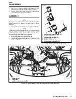
11. See
Figure 6-88.
Slide idler pulley assembly on to studs
(4), install nuts and washers (5) and tighten to 33-35 ft-
lbs (44.74-47.45 Nm).
12. Install front sprocket cover. See
2.30 SPROCKET
COVER
.
CAUTION
Never remove rear axle with swingarm brace removed.
13. See
Figure 6-92.
Tighten rear axle (1) to 48-52 ft-lbs (65-
70 Nm).
14. Tighten rear axle pinch fastener (2) to 40-45 ft-lbs (54-
61 Nm).
15. Install clutch assembly, primary chain and engine
sprocket. See
6.4 PRIMARY DRIVE/CLUTCH
.
16. Install primary cover. See
6.2 PRIMARY CHAIN
.
17. Assemble gearcase. See
3.16 GEARCASE COVER
AND CAM GEARS.
18. Assemble top end. See
3.6 CYLINDER HEAD
.
19. Remove engine from
ENGINE SUPPORT STAND (Part
No. HD-42310/HD-43646 or HD-43682).
20. Install engine in chassis. See
3.4 STRIPPING MOTOR-
CYCLE FOR ENGINE SERVICE
.
21. Fill transmission and engine to proper level with fresh
lubricant. See
1.2 FLUID REQUIREMENTS.
Figure 6-91. Aligning Transmission Sprocket
45°
30°
a0163x6x
1.
Transmission sprocket nut
2.
Transmission sprocket
3.
Line scribed on nut and sprocket
3
2
1
Figure 6-92. Rear Wheel Mounting, Right Side
8420
2
1.
Axle
2.
Pinch bolt fastener
1
Summary of Contents for XB9R 2003
Page 2: ...1 2 Edit Me Printed June 5 2002 12 26 pm ...
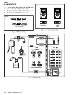
Page 35: ...D 2 2003 Buell XB9R Appendix D HOME Figure D 2 Rear Brake Systems Top View b1115xbx ...
Page 36: ...2003 Buell XB9R Appendix D D 3 HOME Figure D 3 Rear Brake Systems Left Side View b1116xcx ...
Page 47: ...D 14 2003 Buell XB9R Appendix D HOME NOTES ...
Page 49: ......
Page 77: ...1 28 2003 Buell XB9R Maintenance HOME NOTES ...
Page 103: ...1 54 2003 Buell XB9R Maintenance HOME NOTES ...
Page 105: ... 2 ...
Page 191: ......
Page 263: ...3 72 2003 Buell XB9R Engine HOME NOTES ...
Page 299: ...4 2 2003 Buell XB9R Fuel System HOME NOTES ...
Page 385: ...4 88 2003 Buell XB9R Fuel System HOME NOTES ...
Page 421: ...4 124 2003 Buell XB9R Fuel System HOME NOTES ...
Page 423: ......
Page 445: ...5 22 2003 Buell XB9R Starter HOME NOTES ...
Page 447: ......
Page 469: ...6 22 2003 Buell XB9R Drive Transmission HOME NOTES ...
Page 497: ...6 50 2003 Buell XB9R Drive Transmission HOME NOTES ...
Page 499: ......