162
Bosch Rexroth AG
| Tightening Technology
3 608 878 300
System 350
| 3 608 878 300/2019-03
5.3.2
Sequence
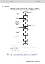
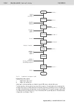
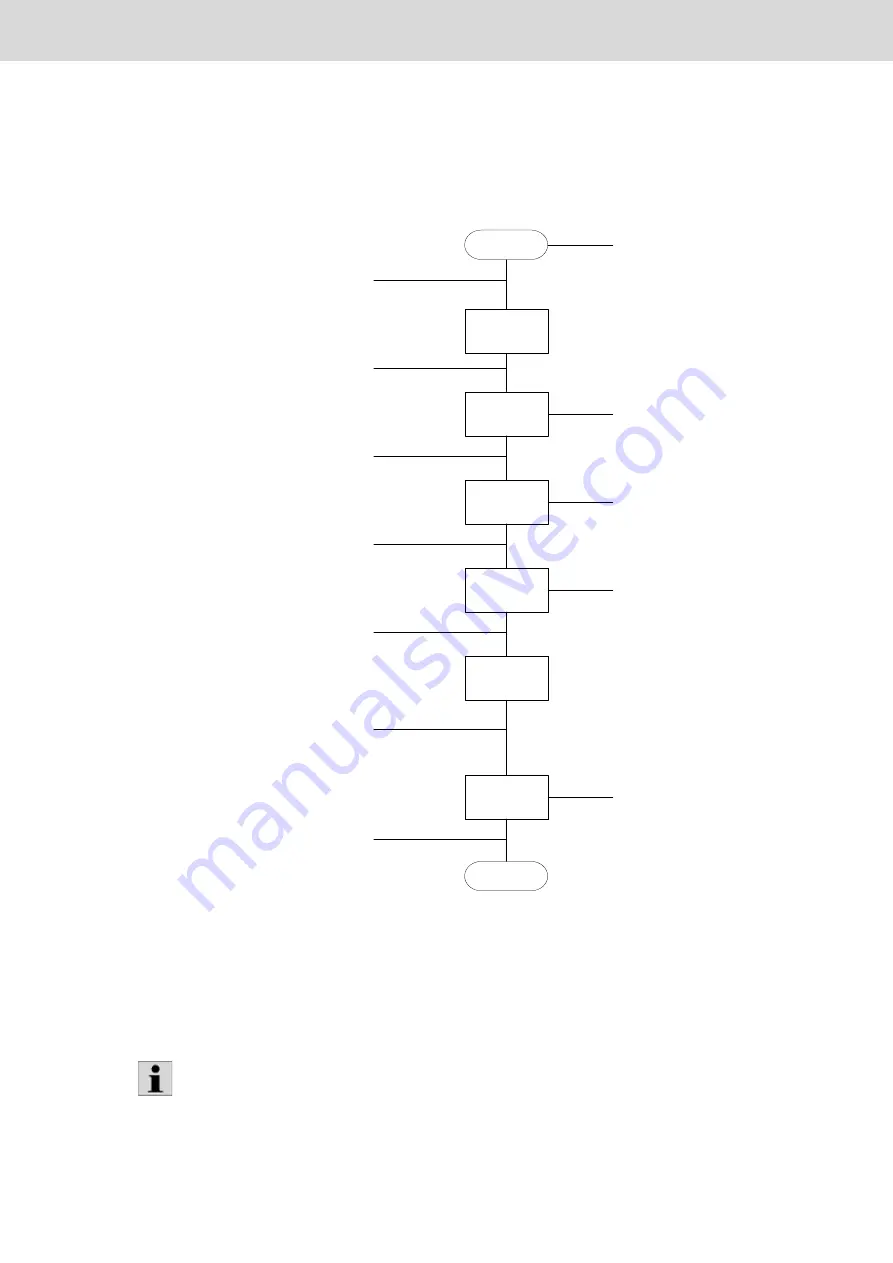
The following flow chart provides an overview of the sequence of the individual control signals and the
subsequent switching conditions between the beginning and end of a simple tightening process. Use of
the individual PLC signals depends on the individual case of application, e.g. "xyByps".
Fig. 5–3:
KE sequence
*: The correct case of application has to be verified. The selection is based on the process.
Explanation on the signals
1
Signal "high" (signal "on")
0
Signal "low" (signal "off")
Subsequent switching conditions are linked by logical AND, unless indicated otherwise.
System ready
Application
selected
Results
deleted
Start application
Application active
FC NF =1
FC Rdy =1
KE NF = 1
KE Rdy = 1
FOxSeq = FOxAck *
FOxRdy = 1
FOxInCy = 0
FOxResRsAll = 1
FOxCyCmp = 0
FOxOK = 0
FOxNOK = 1
ChxyCyCmp = 0
ChxyOK = 0
ChxyNOK = 1
FOxCw = 1
FOxResRsAll = 0
FOxInCy = 1
FOxCyCmp = 0
FOxOK = 0
FOxNOK = 0
FOxRdy = 0
End
Start
Application
completed
FOxCw = 0
FOxInCy = 0
FOxInCy = 1
FOxCyCmp = 1
(FOxOK = 1 AND FOxNOK = 0)
OR
(FOxOK = 0 AND FOxNOK = 1)
FC NF =1
FC En = 1
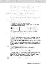
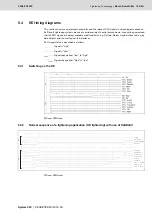
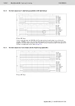
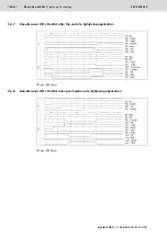
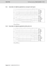
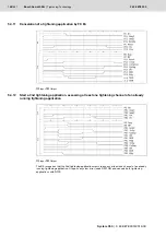
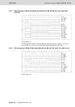
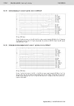
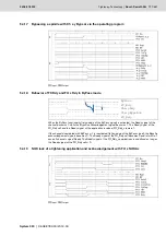
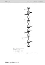
A sequence as described above leads to a signal trend as illustrated in the timing diagram
sequence of a tightening application (OK tightening) with use of ReSRsAll
Summary of Contents for Rexroth Tightening System 350
Page 4: ...4 641 Bosch Rexroth AG Schraubtechnik System 350 3 608 878 300 2019 03 ...
Page 120: ...120 641 Bosch Rexroth AG Tightening Technology 3 608 878 300 System 350 3 608 878 300 2019 03 ...
Page 194: ...194 641 Bosch Rexroth AG Tightening Technology 3 608 878 300 System 350 3 608 878 300 2019 03 ...
Page 638: ...638 641 Bosch Rexroth AG Tightening Technology 3 608 878 300 System 350 3 608 878 300 2019 03 ...

