Service and Maintenance for Mortise Locks
4–56
W Series Service Manual
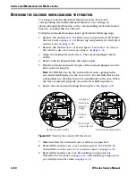
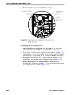
Reinstalling the latch status switch
1. Install the new latch status switch assembly in the case.
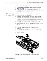
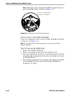
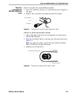
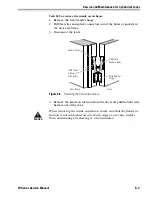
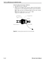
2. Route the latch status switch wires or cable as shown in
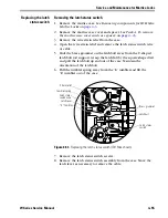
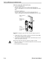
3. Clamp the latch status switch wires or cable in the strain relief. Slide
the strain relief into position on the case. It should lock into place.
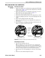
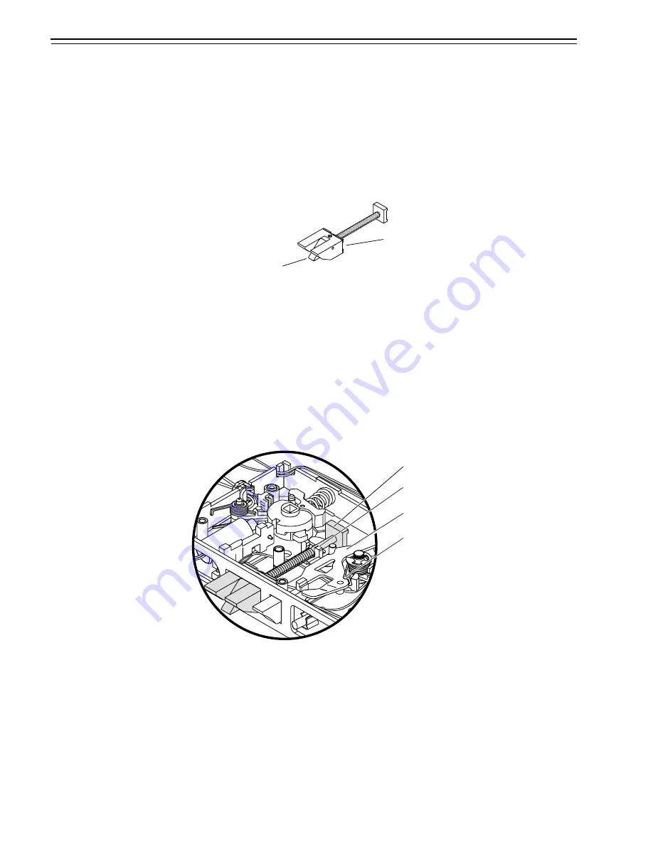
4. Make sure that the latchbolt’s anti-friction latch lever is in position
and place the latchbolt in the case.
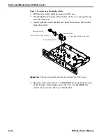
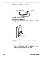
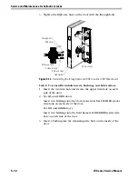
5. Slide the brass grommet on the latchbolt away from the U-shaped
latchbolt rod support. Rest the latchbolt rod into the U-shaped
support. Release the grommet. It should snap into place.
Note:
If you can pull the square-shaped tail out of the rod support,
the latchbolt is not placed properly. Reposition the latchbolt.
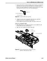
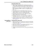
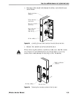
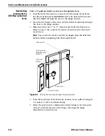
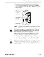
6. Install the “E” tumbler in the case. Make sure that the tumbler spring
rests against the “E” tumbler.
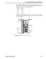
7. Reinstall the mortise case cover and case spacer. See
reinstall the mortise case cover and case spacer:
8. Reinstall the mortise case. See
Task B. To reinstall the mortise case:
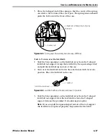
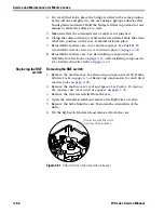
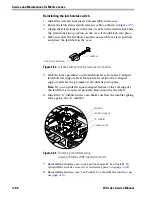
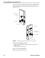
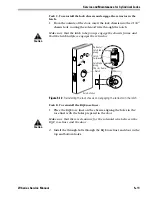
Figure 4.54
Latchbolt with anti-friction latch lever in position
Latchbolt
Anti-friction latch lever
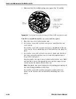
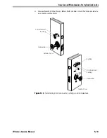
Figure 4.55
Positioning the tumbler spring
(closeup, IDH Max, LHRB orientation shown)
Latchbolt
Latchbolt support
Tumbler spring
“E” tumbler
Summary of Contents for 34HW
Page 1: ......
Page 6: ...Contents vi W Series Service Manual...
Page 38: ...IDH Max Locks Functions and Parts 2 24 W Series Service Manual...
Page 54: ...Electrified Locks Functions and Parts 3 16 W Series Service Manual...
Page 140: ...Service and Maintenance for Cylindrical Locks 5 30 W Series Service Manual...
Page 158: ...Additional Service and Maintenance for IDH Max Locks 6 18 W Series Service Manual...
Page 162: ...Glossary A 4 W Series Service Manual...
Page 164: ...Installation Instructions B 2 W Series Service Manual...