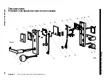
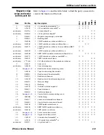
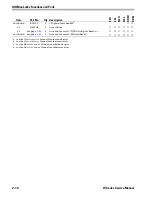
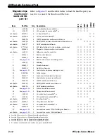
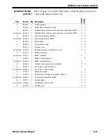

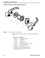
IDH Max Locks Functions and Parts
W Series Service Manual
2–15
R
EADER
CONVERSION
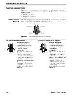
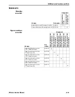
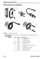
Mortise or
cylindrical reader
conversion
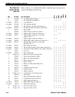
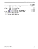
If you want to convert the reader of an existing mortise or cylindrical
IDH Max Lock, use the following table to determine the parts that you
need. You will also need to replace the outside escutcheon
gasket (A60725). This table includes only the parts that are different.
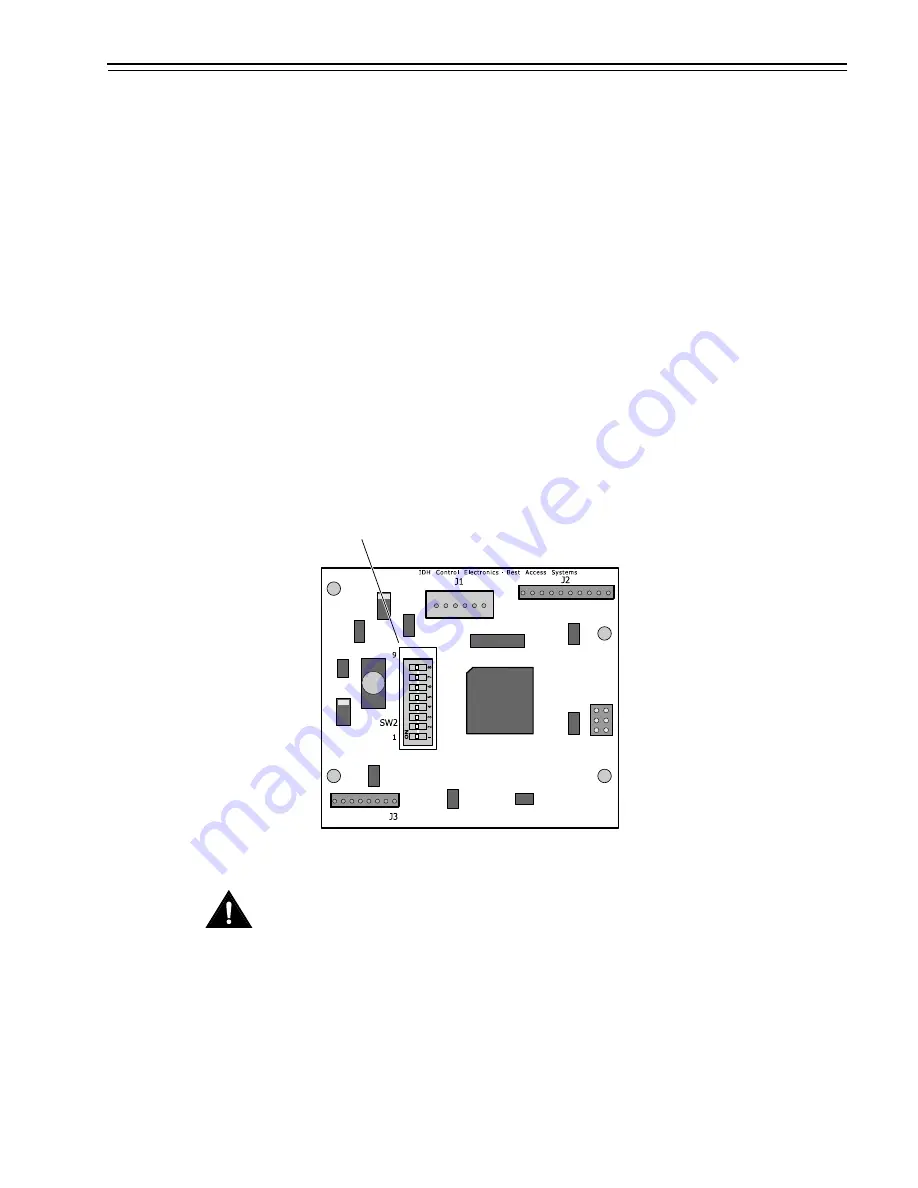
Note:
You do not need to change the position of the DIP switches on
the control electronics circuit board.
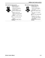
■
By default, switches 1 through 5 are set to ON. These switches are
for possible future applications.
■
By default, switches 6 and 7 are set to ON for automatic baud rate
detection. This setting lets you determine the baud rate for
communication between the lock’s control electronics circuit board
and the panel interface module by setting DIP switches on the panel
interface circuit board.
■
Switch 8 is set to ON only for locks with a magnetic stripe insertion
card reader; it is set to OFF for locks with a magnetic stripe swipe
card reader.
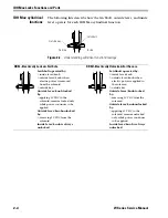
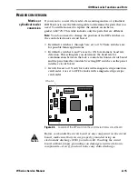
Caution
B
efore you handle the circuit board or any component on the circuit
board, make sure that you are properly grounded using an
electrostatic discharge (ESD) protection kit. Touching the circuit
board without proper grounding can damage sensitive electronic
components—even if you don’t notice any static discharge.
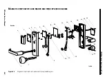
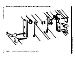
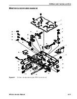
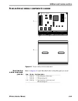
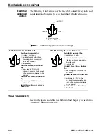
Figure 2.6
Location of the DIP switch on the control electronics circuit board
DIP switch
Summary of Contents for 34HW
Page 1: ......
Page 6: ...Contents vi W Series Service Manual...
Page 38: ...IDH Max Locks Functions and Parts 2 24 W Series Service Manual...
Page 54: ...Electrified Locks Functions and Parts 3 16 W Series Service Manual...
Page 140: ...Service and Maintenance for Cylindrical Locks 5 30 W Series Service Manual...
Page 158: ...Additional Service and Maintenance for IDH Max Locks 6 18 W Series Service Manual...
Page 162: ...Glossary A 4 W Series Service Manual...
Page 164: ...Installation Instructions B 2 W Series Service Manual...