
Service and Maintenance for Mortise Locks
W Series Service Manual
4–39
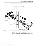
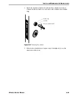
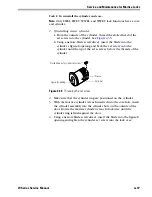
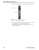
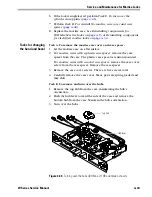
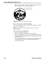
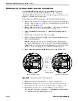
Task G. To reinstall the mortise case faceplate:
Position the faceplate on the lock and install the two faceplate screws.
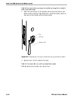
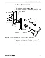
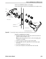
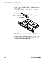
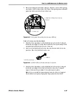
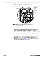
Task H. To reinstall the levers/knobs:
1. From the outside of the door, insert the outside lever/knob and
spindle assembly through the door.
Note:
For lever trim, position the lever so that the handle points
toward the door hinges.
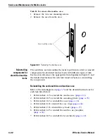
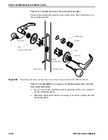
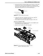
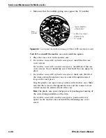
2. Install the inside lever/knob onto the inside spindle.
3. Use a 1/8
″
Allen wrench to install the set screw on the inside
lever/knob.
4.
For knobs
, install the set screw cap.
5. Turn the levers/knobs to check that they work smoothly.
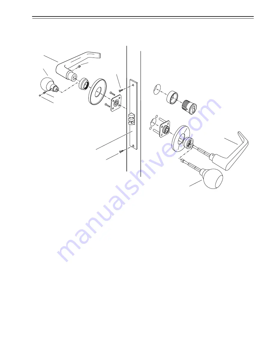
Figure 4.37
Reinstalling the faceplate and the levers/knobs (sectional trim, RH door shown)
Inside of door
Outside of door
Set screw
Set screw cap
Knob
Lever
Knob & spindle assembly
Lever & spindle
assembly
Faceplate screw
Faceplate
Set screw
Faceplate screw
Summary of Contents for 34HW
Page 1: ......
Page 6: ...Contents vi W Series Service Manual...
Page 38: ...IDH Max Locks Functions and Parts 2 24 W Series Service Manual...
Page 54: ...Electrified Locks Functions and Parts 3 16 W Series Service Manual...
Page 140: ...Service and Maintenance for Cylindrical Locks 5 30 W Series Service Manual...
Page 158: ...Additional Service and Maintenance for IDH Max Locks 6 18 W Series Service Manual...
Page 162: ...Glossary A 4 W Series Service Manual...
Page 164: ...Installation Instructions B 2 W Series Service Manual...