

Electrified Locks Functions and Parts
W Series Service Manual
3–5
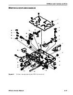
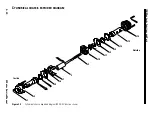
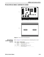
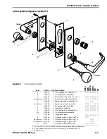
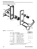
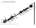
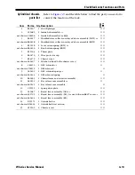
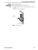
Mortise sectional trim exploded diagram and parts list
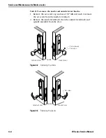
Figure 3.3
Mortise sectional trim exploded diagram
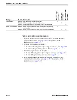
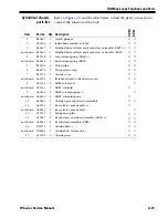
Item
Part no. Qty. Description
EW
EU
EWEL
WW
E
U
WW
E
L
YE
U
YEL
1
(1)
A35454
B62520
1
1
#15 inside lever assembly
a
or
#4 inside knob assembly
a
a. See the
H Series Service Manual
for other lever, knob, rose, and cylinder styles.
■
■
■
■
■
■
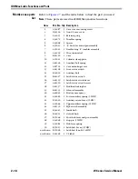
2
A34131
2 Rose ring for lever trim
or
■
■
■
■
■
■
not shown
B34544
2 Rose ring for knob trim
■
■
■
■
■
■
3
A34129
2 Rose
a
■
■
■
■
■
■
4
B35029
1 Mounting plate assembly
■
■
■
■
■
■
5
(5)
A35455
A35084
1
1
#15 outside lever assembly
a
or
#4 outside knob assembly
a
■
■
■
■
■
■
6
B35101
1 Cylinder ring for 6-pin core
b
or
b. Each cylinder ring requires one wavy washer, part number B34115.
■
■
not shown
B35103
1 Cylinder ring for 7-pin core
b
or
■
■
not shown
B35103
2 Cylinder ring for 6-pin core
b
or
■
■
not shown
B35105
2 Cylinder ring for 7-pin core
b
■
■
7
1E74
1 Cylinder
a
with A06419 cam
■
■ ■
c
c. Requires two.
■
c
1
2
3
4
3
2
5
6
7
Inside
Outside
1
5
Summary of Contents for 34HW
Page 1: ......
Page 6: ...Contents vi W Series Service Manual...
Page 38: ...IDH Max Locks Functions and Parts 2 24 W Series Service Manual...
Page 54: ...Electrified Locks Functions and Parts 3 16 W Series Service Manual...
Page 140: ...Service and Maintenance for Cylindrical Locks 5 30 W Series Service Manual...
Page 158: ...Additional Service and Maintenance for IDH Max Locks 6 18 W Series Service Manual...
Page 162: ...Glossary A 4 W Series Service Manual...
Page 164: ...Installation Instructions B 2 W Series Service Manual...