
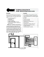

Installation Instructions for 34HW–35HW IDH Max Mortise Locks
BEST ACCESS SYSTEMS
Indianapolis, Indiana
2
Components checklist
Site survey
Use the following survey to record information about the
installation site. You need this information to determine
field wiring needs, select a power supply, and determine
how to prepare the door for the lock.
Lock information
Lock function:
❑
EEL–Electrically locked with key
❑
EEU–Electrically unlocked with key
❑
NEL–Electrically locked without key
❑
NEU–Electrically unlocked without key
Power source for lock:
❑
Separate power supply
❑
Power provided through panel interface module
Power source for panel interface module:
❑
Separate power supply
❑
Power provided through access control panel
Distance of lock site from lock power source: feet
Distance of lock site from panel interface module site:
feet
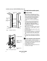
Door information
Door handing and bevel:
❑
Left hand (LH)
❑
Left hand, reverse bevel (LHRB)
❑
Right hand (RH)
❑
Right hand, reverse bevel (RHRB)
Door thickness: inches (1 3/4
″
– 3
″ )
Environment information
Ambient temperature:
❑
Is within specifications. See the tables below.
This product meets the following Locked Door Outdoor
test requirements for ANSI/BHMA 156.25:
This product meets the following Full Indoor test
requirements for ANSI/BHMA 156.25:
Side of door
Range
Inside
+66°F to +74°F (+19°C to +23°C)
Outside
–31°F to +151°F (–35°C to +66°C)
Side of door
Range
Inside and outside
+32°F to +120°F (0°C to +49°C)
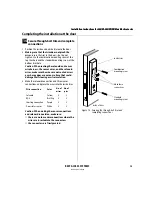
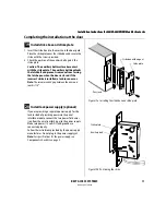
Use the following checklist to make sure that you have the
items necessary to install the components provided with
your 34HW–35HW IDH Max Mortise Lock.
Components provided in the box:
❑
Mortise case assembly
❑
Mortise case faceplate
❑
Inside escutcheon assembly with field wire harness
❑
Inside escutcheon access door
❑
Outside escutcheon assembly
❑
Inside and outside mounting plates
❑
Inside knob/lever
❑
Outside knob/lever & spindle assembly
❑
Cylinder assembly (for use with EEL and EEU functions
only)
❑
Mortise screw package
❑
Trim hole insert package
❑
Plastic bushing package
❑
Escutcheon screw package
❑
Panel interface module
❑
Strike
❑
Strike box with magnet
❑
Spacer (for 6-pin cores)
❑
Bar code ID sticker (for your records)
Other items you’ll need:
❑
Power supply for one IDH Max Mortise Lock (if you’re
providing a separate power supply): regulated;
12 volts DC at 1.1 amps
Note:
If you intend to power more than one lock with the
same power supply, calculate the amperage for the
power supply by multiplying 1.1 by the number of
IDH Max Mortise Locks (.85 by the number of IDH Max
Cylindrical locks).
❑
Power supply for the panel interface module (if you’re
providing a separate power supply): 12 volts DC at
.1 amp
❑
Wire transfer hinge: 8 conductors min.; 28 AWG min.
continued
Summary of Contents for 34HW
Page 1: ......
Page 6: ...Contents vi W Series Service Manual...
Page 38: ...IDH Max Locks Functions and Parts 2 24 W Series Service Manual...
Page 54: ...Electrified Locks Functions and Parts 3 16 W Series Service Manual...
Page 140: ...Service and Maintenance for Cylindrical Locks 5 30 W Series Service Manual...
Page 158: ...Additional Service and Maintenance for IDH Max Locks 6 18 W Series Service Manual...
Page 162: ...Glossary A 4 W Series Service Manual...
Page 164: ...Installation Instructions B 2 W Series Service Manual...