Service and Maintenance for Cylindrical Locks
5–28
W Series Service Manual
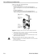
For electrified locks
■
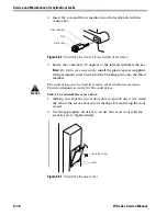
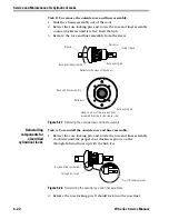
Install the rose.
■
Reinstall the inside lever/knob. See
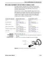
Removing and
reinstalling the door
status switch and
magnet assembly
for IDH Max
Cylindrical Locks
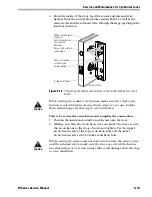
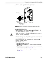
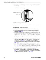
Removing the door status and switch magnet assembly
1. Remove the inside lever/knob. See
.
2. Remove the access door. See
Task C. To remove the access door:
.
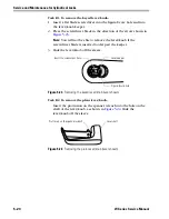
3. Remove the upper and lower escutcheon screws from the inside
escutcheon.
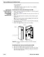
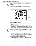
Note:
You can let the inside escutcheon dangle from the field wire
harness while completing this task.
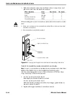
4. Disconnect the door status switch connector from the sensor and
solenoid wire harness.
5. Remove the magnet from the hole in the door frame.
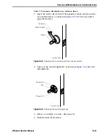
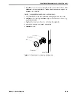
Reinstalling the door status and switch magnet assembly
1. Insert the new magnet in the hole in the door frame.
2. Insert the door status switch assembly into the door status switch
hole in the edge of the door, feeding the connectors out the wire
hole to the inside of the door.
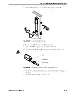
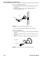
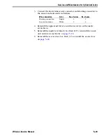
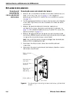
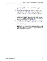
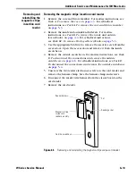
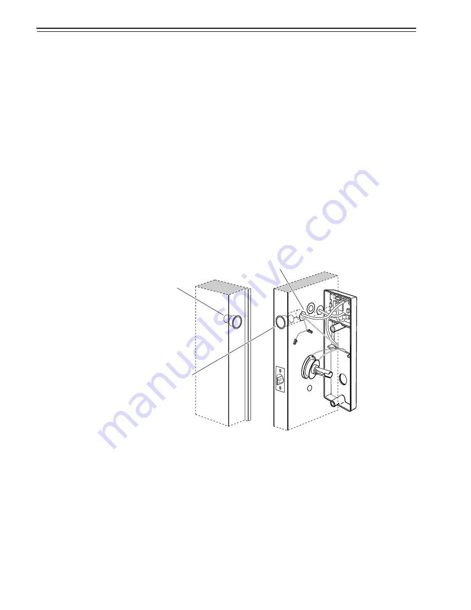
Figure 5.33
Removing and reinstalling the door status switch and magnet
assembly
Magnet
Wire hole
Inside of door
Door status switch
Door jamb
Summary of Contents for 34HW
Page 1: ......
Page 6: ...Contents vi W Series Service Manual...
Page 38: ...IDH Max Locks Functions and Parts 2 24 W Series Service Manual...
Page 54: ...Electrified Locks Functions and Parts 3 16 W Series Service Manual...
Page 140: ...Service and Maintenance for Cylindrical Locks 5 30 W Series Service Manual...
Page 158: ...Additional Service and Maintenance for IDH Max Locks 6 18 W Series Service Manual...
Page 162: ...Glossary A 4 W Series Service Manual...
Page 164: ...Installation Instructions B 2 W Series Service Manual...