


Installation Instructions for 34HW–35HW IDH Max Mortise Locks
BEST ACCESS SYSTEMS
Indianapolis, Indiana
5
Installation Instructions for 34HW–35HW IDH Max Mortise Locks
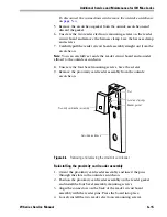
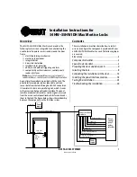
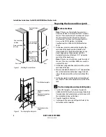
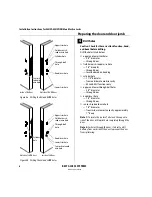
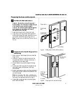
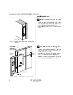
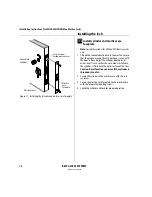
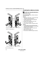
Preparing the door and door jamb
3
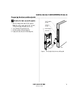
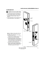
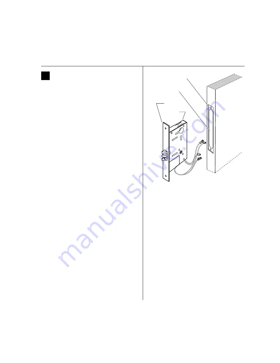
Mortise for lock case and faceplate
1 Mortise the edge of the door for the lock case.
Note:
The mortise cavity depth of 4 5/8
″
includes
clearance for wiring behind the mortise case.
2 Insert the lock in the mortise cavity.
3 Mark the outline of the lock faceplate.
4 Remove the lock. Mortise to fit the faceplate.
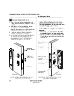
Figure 3
Mortising for the lock case and faceplate
Door
Lock faceplate
mortise
Lock case
mortise
Lock faceplate
Lock case
Summary of Contents for 34HW
Page 1: ......
Page 6: ...Contents vi W Series Service Manual...
Page 38: ...IDH Max Locks Functions and Parts 2 24 W Series Service Manual...
Page 54: ...Electrified Locks Functions and Parts 3 16 W Series Service Manual...
Page 140: ...Service and Maintenance for Cylindrical Locks 5 30 W Series Service Manual...
Page 158: ...Additional Service and Maintenance for IDH Max Locks 6 18 W Series Service Manual...
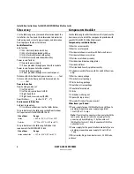
Page 162: ...Glossary A 4 W Series Service Manual...
Page 164: ...Installation Instructions B 2 W Series Service Manual...