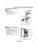
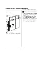
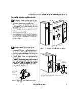
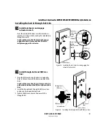
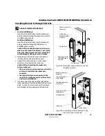
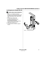
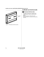
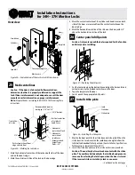
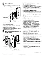
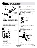

Installation Instructions for 83KW/93KW–85KW/95KW IDH Max Cylindrical Locks
BEST ACCESS SYSTEMS
Indianapolis, Indiana
21
Installation Instructions for 83KW/93KW–85KW/95KW IDH Max Cylindrical Locks
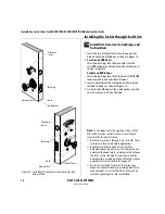
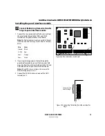
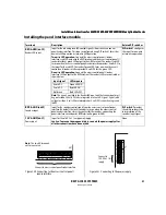
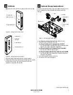
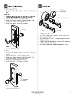
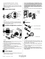
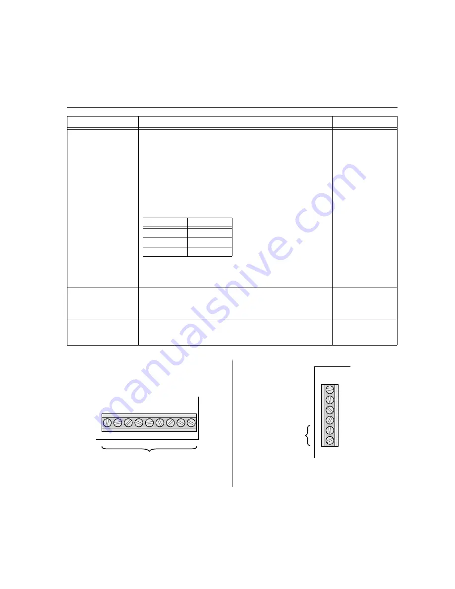
Installing the panel interface module
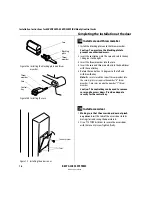
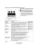
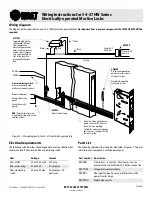
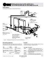
RED & GRN (on J2)
Reader LED input
Input for the red and green LED control signal(s) from the access control
panel/reader interface. This input is configured using DIP switch 1 for either
one-wire LED operation or two-wire LED operation.
Two-wire LED operation:
Connect the access control panel’s/reader
interface’s red LED output to the RED terminal and the access control panel’s/
reader interface’s green LED output to the GRN terminal. The reader’s red LED
turns on when the access control panel/reader interface provides 0 volts DC to
the input for the red LED. The reader’s green LED turns on when the access
control panel/reader interface provides 0 volts DC for the green LED.
One-wire LED operation:
Connect the access control panel’s/reader
interface’s LED output to the RED terminal. The reader’s LEDs are controlled as
shown below.
Note:
The signals provided to the Reader LED input and the Sounder input must
be greater than 3.5 volts DC to be interpreted as a 5 volts DC signal. Signals with
voltage less than .8 volts DC are interpreted as 0 volts DC (connection to ground
(GND).
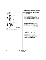
DIP switch 1
configures
this input for one-wire
or two-wire operation.
BPR & GND (on J2)
Sounder input
Input for the sounder control signal from the access control panel/reader
interface. By default, the lock’s sounder turns on when the access control
panel/reader interface closes the contact for the sounder, connecting the
panel interface circuit board’s BPR terminal to ground (GND).
DIP switch 7
provides
the ability to invert the
interpretation of the
sounder input signal.
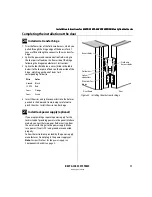
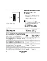
12V & GND (on J1)
Power input
Input for 12 volts DC at .1 amp power supply.
Caution:
To prevent damage and injury, connect the power supply after
all other connections have been made.
None
Terminals
Description
Related DIP switches
Input signal
LED response
0 volts DC
Green LED ON
5 volts DC
Red LED ON
Not driven
Both LEDs OFF
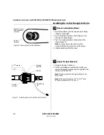
J2
D0 D1 RED GRN BPR GND
NC CP
NC
Connect to access control panel/reader interface.
Figure 23b Connecting to the access control panel/
reader interface
Note:
The two NC terminals
on J2 are not used.
GND
J1
12V
COM+
COM-
GND
12V
Connect to
12 VDC at .1 A
supply.
Figure 23c Connecting to the power supply
Summary of Contents for 34HW
Page 1: ......
Page 6: ...Contents vi W Series Service Manual...
Page 38: ...IDH Max Locks Functions and Parts 2 24 W Series Service Manual...
Page 54: ...Electrified Locks Functions and Parts 3 16 W Series Service Manual...
Page 140: ...Service and Maintenance for Cylindrical Locks 5 30 W Series Service Manual...
Page 158: ...Additional Service and Maintenance for IDH Max Locks 6 18 W Series Service Manual...
Page 162: ...Glossary A 4 W Series Service Manual...
Page 164: ...Installation Instructions B 2 W Series Service Manual...