
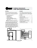
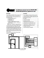
Installation Instructions for 34HW–35HW IDH Max Mortise Locks
BEST ACCESS SYSTEMS
Indianapolis, Indiana
13
Installation Instructions for 34HW–35HW IDH Max Mortise Locks
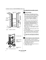
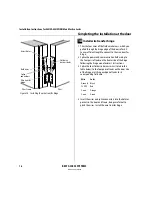
Completing the installation at the door
14
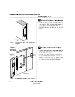
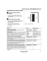
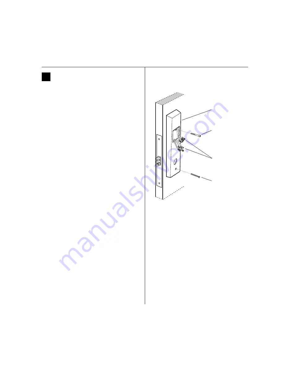
Secure through-bolt trim and complete
connections
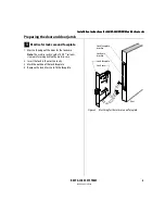
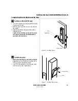
1 Position the inside and outside trim onto the door.
2
Making sure that the trim does not pinch the
wires
, secure the trim to the door—but do not
tighten. Use the combination mounting screw at the
top trim hole and the standard mounting screw at the
bottom trim hole.
Caution:
When routing the solenoid and sensor
wire harness, the sensor wires, and the solenoid
wires, make sure the wires are not routed across
any sharp edges or over any surface that could
damage their sleeving or wire insulation.
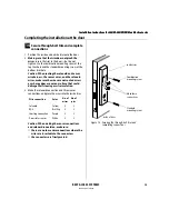
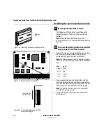
3 Make the solenoid connection and three sensor
connections, and place the wires into the inside trim.
Caution:
When making the sensor connections
and solenoid connection, make sure:
■
there are no loose wire connections where the
wires are inserted into the connectors
■
the connectors are firmly mated.
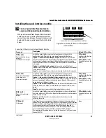
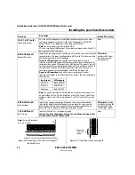
Wire connection
Color
No. of
wires
No. of
pins
Solenoid
Yellow
2
3
RQE
Brn/Org
2
3
Shorting connection
Purple
2
2
Door status sensor
White
2
2
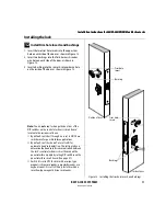
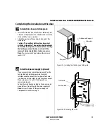
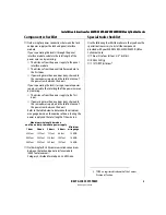
Figure 14 Securing the through-bolt trim and
completing connections
Combination
mounting screw
Standard
mounting screw
Make these
connections.
Inside of door
Inside trim
Summary of Contents for 34HW
Page 1: ......
Page 6: ...Contents vi W Series Service Manual...
Page 38: ...IDH Max Locks Functions and Parts 2 24 W Series Service Manual...
Page 54: ...Electrified Locks Functions and Parts 3 16 W Series Service Manual...
Page 140: ...Service and Maintenance for Cylindrical Locks 5 30 W Series Service Manual...
Page 158: ...Additional Service and Maintenance for IDH Max Locks 6 18 W Series Service Manual...
Page 162: ...Glossary A 4 W Series Service Manual...
Page 164: ...Installation Instructions B 2 W Series Service Manual...