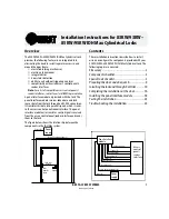

Installation Instructions for 83KW/93KW–85KW/95KW IDH Max Cylindrical Locks
BEST ACCESS SYSTEMS
Indianapolis, Indiana
5
Installation Instructions for 83KW/93KW–85KW/95KW IDH Max Cylindrical Locks
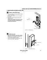
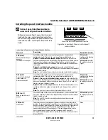
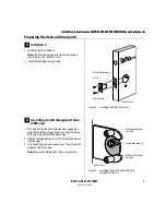
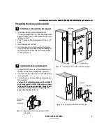
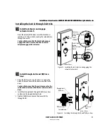
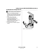
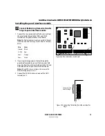
Preparing the door and door jamb
2
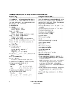
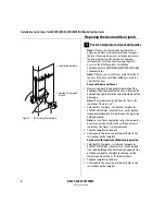
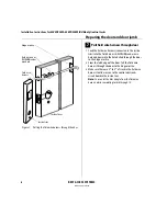
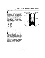
Drill holes and mortise for latch face
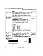
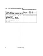
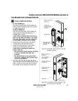
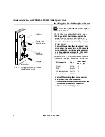
1 Drill the holes listed below:
■
upper and lower trim holes
— 5/8
″
diameter
— through door
■
door status switch & LH/LHRB reader wire hole
— 7/8
″
diameter
— through door
■
field harness & RH/RHRB reader wire hole
— 7/8
″
diameter
— through door
■
door status switch hole
— 1
″
diameter
— meets door status switch & LH/LHRB reader wire
hole
■
solenoid wire hole
— 3/8
″
diameter
— through door
— before drilling chassis hole
■
chassis hole
— 2 1/8
″
diameter
— through door
— after drilling solenoid wire hole
■
latch hole
— 1
″
diameter
— meets chassis hole
Note 1:
To locate the center of a hole on the opposite
side of the door, drill a pilot hole completely through the
door.
Note 2:
For holes through the door, it is best to drill
halfway from each side of the door to prevent the door
from splintering.
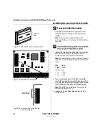
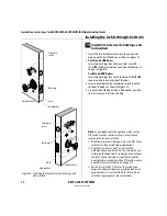
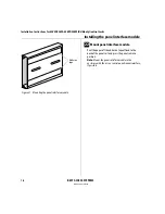
2 Mortise the edge of the door to fit the latch face.
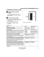
Figure 2
Drilling holes and mortising for the latch face
Door status
switch hole
Latch hole
Upper trim
hole
Door status
switch & LH/
LHRB reader
wire hole
Solenoid wire
hole
Chassis hole
Lower trim
hole
Inside of door
Latch face
mortise
Field harness
& RH/RHRB
reader wire
hole
Summary of Contents for 34HW
Page 1: ......
Page 6: ...Contents vi W Series Service Manual...
Page 38: ...IDH Max Locks Functions and Parts 2 24 W Series Service Manual...
Page 54: ...Electrified Locks Functions and Parts 3 16 W Series Service Manual...
Page 140: ...Service and Maintenance for Cylindrical Locks 5 30 W Series Service Manual...
Page 158: ...Additional Service and Maintenance for IDH Max Locks 6 18 W Series Service Manual...
Page 162: ...Glossary A 4 W Series Service Manual...
Page 164: ...Installation Instructions B 2 W Series Service Manual...