Service and Maintenance for Cylindrical Locks
W Series Service Manual
5–9
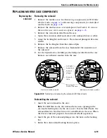
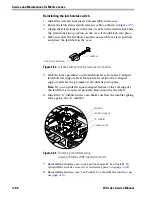
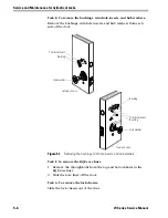
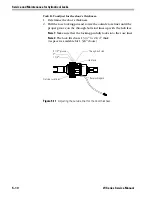
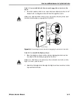
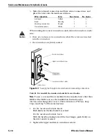
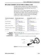
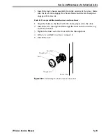
6. Splice the four field wire harness leads (listed in the table below) to
the four pairs of leads on the door side of the hinge, matching each
pair of leads to its corresponding field wire.
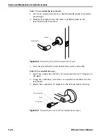
7. Insert the wires and splice connectors into the holes or pockets in
the door and frame, being careful not to pinch the wires. Install the
wire transfer hinge.
Wire
Color
Ground
Black
12 VDC
Red
Com+
Orange
Com–
Green
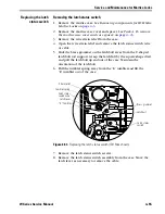
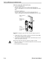
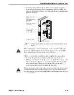
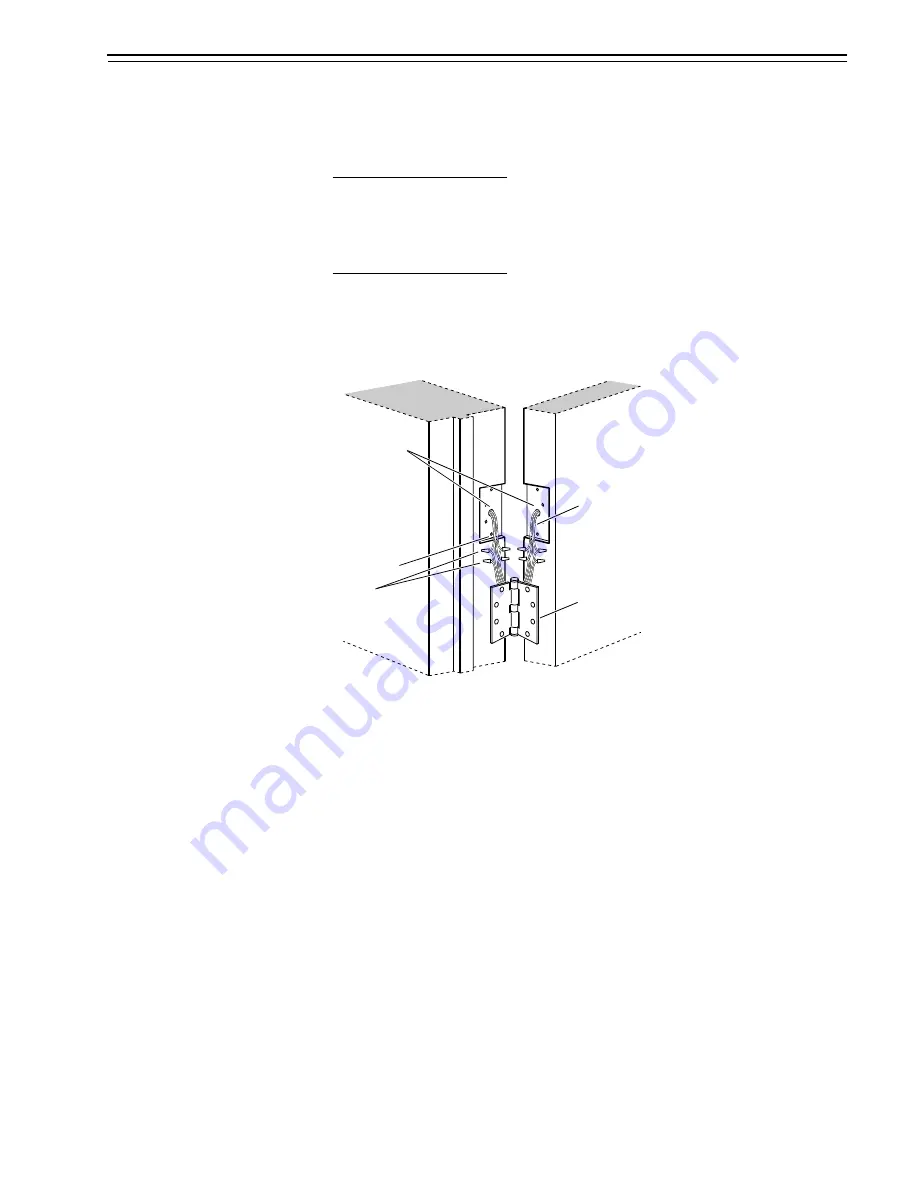
Figure 5.10
Installing the wire transfer hinge
Access holes
Field wire
harness leads
Wire transfer
hinge
Door frame
Field wires
Splice
connectors
Door
Summary of Contents for 34HW
Page 1: ......
Page 6: ...Contents vi W Series Service Manual...
Page 38: ...IDH Max Locks Functions and Parts 2 24 W Series Service Manual...
Page 54: ...Electrified Locks Functions and Parts 3 16 W Series Service Manual...
Page 140: ...Service and Maintenance for Cylindrical Locks 5 30 W Series Service Manual...
Page 158: ...Additional Service and Maintenance for IDH Max Locks 6 18 W Series Service Manual...
Page 162: ...Glossary A 4 W Series Service Manual...
Page 164: ...Installation Instructions B 2 W Series Service Manual...