


Installation Instructions for 34HW–35HW IDH Max Mortise Locks
BEST ACCESS SYSTEMS
Indianapolis, Indiana
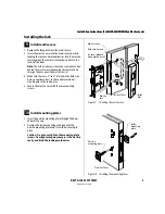
Installing the lock
8
7
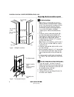
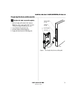
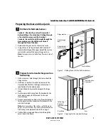
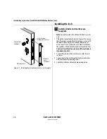
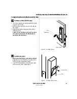
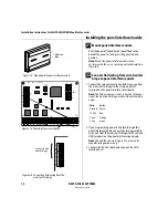
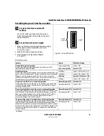
Mortise for strike box and strike plate
1 On the door jamb, locate the horizontal centerline of
the strike (3/8
″
above the centerline of the lock), as
well as the vertical centerline of the strike.
2 Mortise the door jamb to fit the strike box and strike
plate.
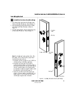
8
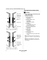
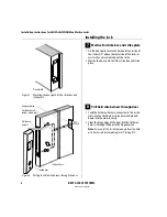
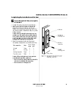
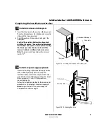
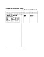
Pull field wire harness through door
1 Feed the field wire harness (connected to the inside
trim) into the field harness & reader wire hole and
down into the mortise cavity.
2 From the hinge edge of the door, fish the field wire
harness through the door to the hinge mortise.
Note:
You can let the inside trim dangle from the field
wire harness while completing tasks 9 through 13.
Figure 7
Mortising the door jamb for the strike box and
strike plate
Door jamb
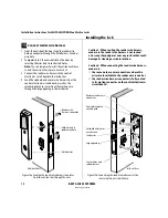
Figure 8
Pulling the field wire harness through the door
Hinge mortise
Field wire
harness
Inside trim
Field harness &
reader wire hole
Inside of door
Summary of Contents for 34HW
Page 1: ......
Page 6: ...Contents vi W Series Service Manual...
Page 38: ...IDH Max Locks Functions and Parts 2 24 W Series Service Manual...
Page 54: ...Electrified Locks Functions and Parts 3 16 W Series Service Manual...
Page 140: ...Service and Maintenance for Cylindrical Locks 5 30 W Series Service Manual...
Page 158: ...Additional Service and Maintenance for IDH Max Locks 6 18 W Series Service Manual...
Page 162: ...Glossary A 4 W Series Service Manual...
Page 164: ...Installation Instructions B 2 W Series Service Manual...