Service and Maintenance for Mortise Locks
4–48
W Series Service Manual
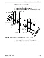
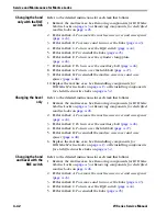
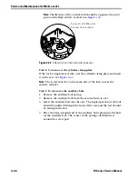
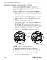
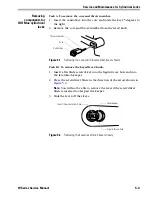
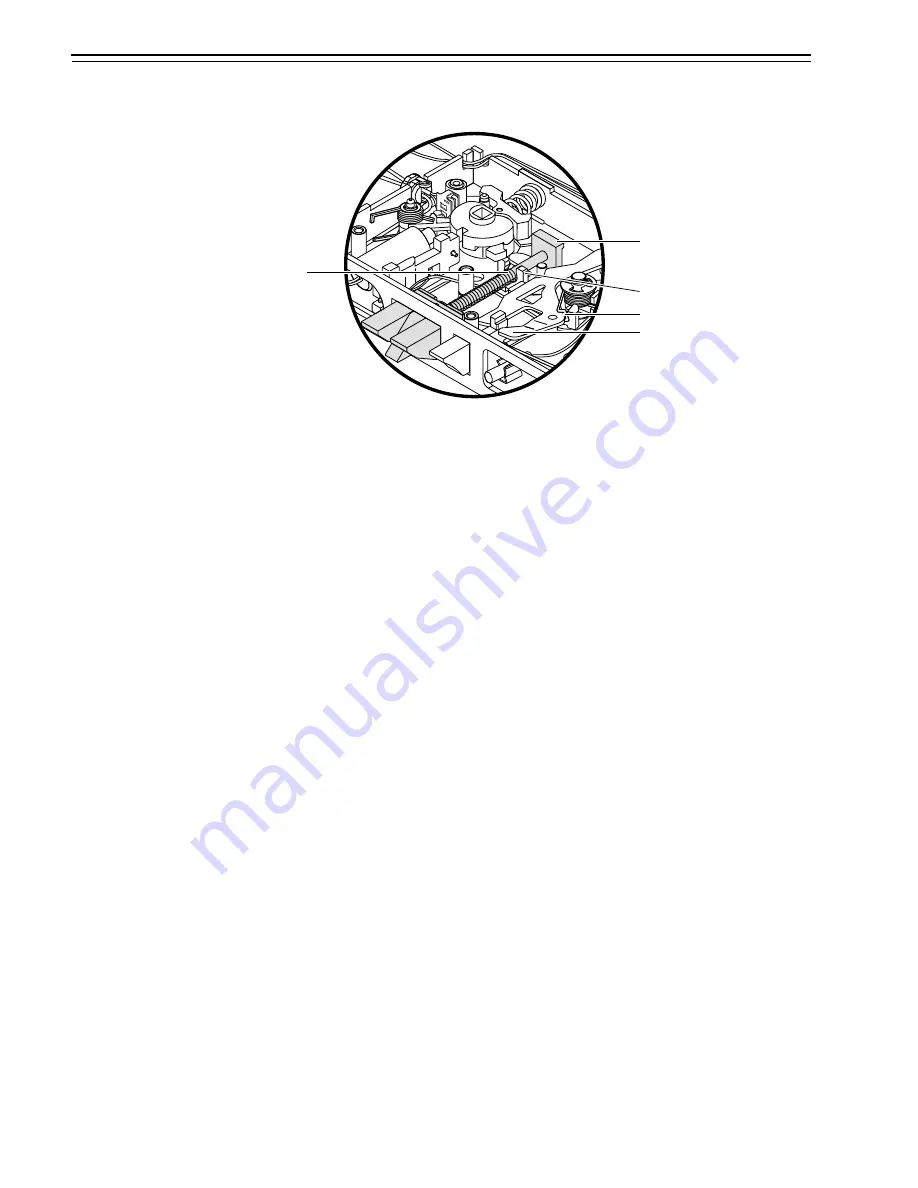
4. Make sure that the tumbler spring rests against the “E” tumbler.
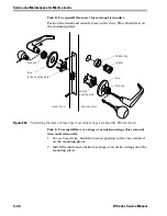
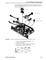
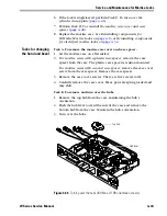
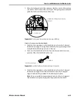
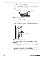
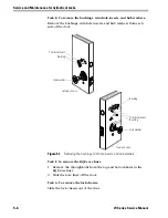
Task H. To reinstall the mortise case cover and case spacer:
1. Place the case cover on the mortise case.
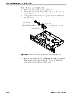
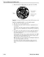
2.
For mortise cases with a plastic case spacer
, install the five case
cover screws.
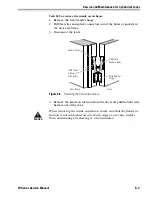
For mortise cases with a metal case spacer
, install four of the case
cover screws. Do not install the screw that holds the case spacer in
place.
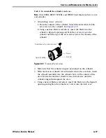
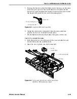
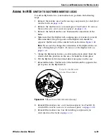
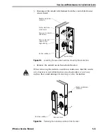
3.
For mortise cases with a plastic case spacer
, make sure that all of
the wires exiting the mortise case are routed through the raised
loop on the case spacer.
Snap the plastic case spacer into position on the mortise case. Make
sure that the wires are flat against the case and the connectors are
routed toward the armored front of the case.
Note:
The plastic case spacer helps prevent pinching and nicking of
the wires during installation of the trim.
For mortise cases with a metal case spacer
, position the case
spacer on the mortise case and install the remaining case cover
screw.
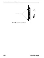
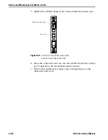
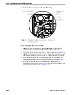
Figure 4.47
Turning over the latchbolt (closeup, IDH Max, LHRB orientation shown)
Square-shaped tail
of the latchbolt
Latchbolt rod support
Tumbler spring
“E” tumbler
Brass
grommet
Summary of Contents for 34HW
Page 1: ......
Page 6: ...Contents vi W Series Service Manual...
Page 38: ...IDH Max Locks Functions and Parts 2 24 W Series Service Manual...
Page 54: ...Electrified Locks Functions and Parts 3 16 W Series Service Manual...
Page 140: ...Service and Maintenance for Cylindrical Locks 5 30 W Series Service Manual...
Page 158: ...Additional Service and Maintenance for IDH Max Locks 6 18 W Series Service Manual...
Page 162: ...Glossary A 4 W Series Service Manual...
Page 164: ...Installation Instructions B 2 W Series Service Manual...