


Learning Advanced Features
138
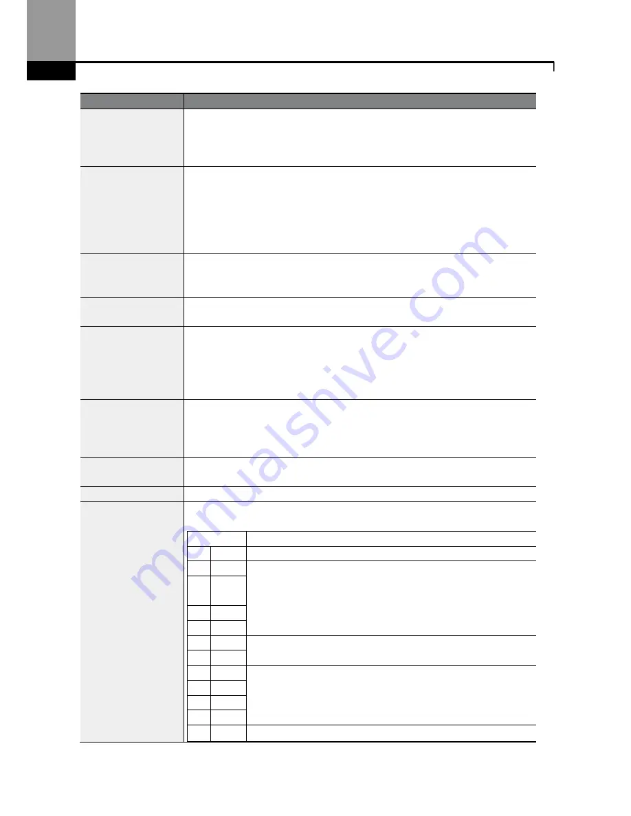
Code
Description
AP.22 PID P-Gain,
AP.26 P Gain Scale
Sets the output ratio for differences (errors) between reference (setpoint)
and feedback. If the Pgain is set to 50%, then 50% of the error is output. The
setting range for Pgain is 0.0-1,000%. For ratios below 0.1%, use AP.26 (P
Gain Scale).
AP.23 PID I- Time
Sets the time to output accumulated errors. When the error is 100%, the
time taken for 100% output is set. When the integral time (PID I-Time) is set
to 1 second, 100% output occurs after 1 second of the error remaining at
100%. Differences in a normal state can be reduced by PID I Time. Also, a
digital input can be set to 21 (I-Term Clear) to clear all of the accumulated
errors.
AP.24 PID D-Time
Sets the output volume for the rate of change in errors. If the differential
time (PID D-Time) is set to 1ms and the rate of change in errors per sec is
100%, output occurs at 1% per 10ms.
AP.25 PID F-Gain
Sets the ratio that adds the target to the PID output. Adjusting this value
leads to a faster response.
AP.27 PID Out LPF
Used when the output of the PID controller changes too fast or the entire
system is unstable due to severe oscillations. In general, a lower value
(default value=0) is used to speed up response time, but in some cases a
higher value increases stability. The higher the value, the more stable the
PID controller output is, but the slower the response time.
AP.28 PID Mode
Process PID (0) or Normal PID (1). Process PID is used in applications when
the monitored (process) variable increases, the response is to decrease the
output of the inverter. In Normal PID applications, as the process variable
increases, the response is to increase the output of the inverter.
AP.29 PID Limit Hi,
AP.30 PID Limit Lo
Limits the output frequency of the controller.
AP.32 PID Out Scale Adjusts the volume of the controller output.
AP.42 PID Unit Sel
Sets the unit of the control variable.
Setting
Function
0
%
Displays a percentage without a physical quantity given.
1
Bar
Various units of pressure can be selected.
2
mBa
r
3
Pa
4
kPa
5
Hz
Displays the inverter output frequency or the motor rotation
speed.
6
rpm
7
V
Displays in voltage/current/power/horsepower.
8
I
9
kW
10 HP
11
°C
Displays in Celsius or Fahrenheit.
Summary of Contents for Rsi S Series
Page 2: ......
Page 6: ......
Page 12: ...Preparing the Installation 0...
Page 22: ...Preparing the Installation 10...
Page 70: ...LearningAdvanced Features 58...
Page 152: ...LearningAdvanced Features 140 PID controlblock diagram...
Page 224: ...LearningAdvanced Features 212...
Page 356: ...344...
Page 362: ...Maintenance 350...
Page 381: ...369 TechnicalSpecification...
Page 397: ......