background image

Copiscan 8000 Spectrum Operator Manual 

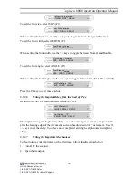
STRING  FONT*  DELAY

Set text to be printed


To set the font size, select SIZE (F1) 


SIZE*  WIDTH   ANGLE

Font Size is Large


When setting the font size, use the +/- keys to toggle between Large and Normal. 

To set the font width, select WIDTH (F2). 


SIZE   WIDTH*  ANGLE

Font Size is  Large


When setting the font width, use the +/- keys to toggle between Normal and Double. 


SIZE   WIDTH*  ANGLE

Font Width is  Normal


To set the font angle, select ANGLE (F3). 


SIZE   WIDTH   ANGLE*

Font Size is  Large


When setting the font angle, use the +/- keys to toggle between 0

°

, 90

°

, 180

°

, and 270°. 


SIZE   WIDTH   ANGLE*

Font Rotation is 

180°


Press the UP key to exit these menus. 

5.5.1.6 

Setting the Imprint Delay from the Start of Page 

Return to the SETUP menu and select DELAY (F3).  

Front Printer:Off
ON/OFF REFILL  SETUP


STRING  FONT   DELAY*

Print Delay is

1.5"


The imprint string can begin immediately as a document gets scanned, or up to 13.5” 
after the leading edge of the document and can be adjusted in 0.1” increments. Use the 
+/- keys to set the delay. You have now completed setting the alphanumeric imprint 
string. 

5.5.1.7 

Setting the Imprinter Mechanism 

To begin using your imprinter for the first time, follow the directions below: 

1.  Turn OFF the scanner.  

2.  Open the transport. 


46

www.bbhscanners.com 
1-800-SCAN-494 Sales 


1-800-SCAN-495 Technical Support


Summary of Contents for 8000

Page 1: ...Operator Manual Böwe Bell Howell S005149 Rev C June 2004 2004 Copyright Böwe Bell Howell Scanners L L C All rights reserved ...

Page 2: ...3353 2004 Böwe Bell Howell Scanners L L C All Rights Reserved All material in this publication is confidential and is to be used by and distributed to authorized personnel of the purchaser only All intellectual property rights remain the property of Böwe Bell Howell Scanners L L C No part of this publication may be reproduced distributed modified displayed transmitted stored in a retrieval system ...

Page 3: ...the instructions may cause harmful interference with radio communications However there is no guarantee that interference will not occur in a particular installation If this equipment does cause harmful interference to radio or television reception which can be determined by turning the equipment off and on the user is encouraged to try to correct the interference by one or more of the following m...

Page 4: ... 5 OPERATION 19 5 1 POWER UP POWER DOWN 19 5 2 CONTROL PANEL 20 5 3 NORMAL OPERATING ROUTINE 26 5 4 SYSTEM SETUP 34 5 5 OPTIONAL IMPRINTER 42 5 6 SCANNING DOCUMENTS 50 5 7 MULTIFEED DETECTOR 51 5 8 DOCUMENT SKEW 51 5 9 CLEARING SCANNER DOCUMENT JAMS 51 6 OPERATOR MAINTENANCE 53 6 1 MAINTENANCE SCHEDULE 53 6 2 PERPETUAL COUNTERS 54 6 3 CODE REVISION NUMBERS 54 6 4 CLEANING THE GLASS FLAT 55 6 5 CAL...

Page 5: ...EDER SKIMMER ASSEMBLY ROLLERS 70 6 14 REPLACING THE FEEDER SEPARATOR ROLLER SLEEVE ASSEMBLY 72 6 15 CLEANING OR REPLACING THE FEEDER SEPARATOR ROLLER 74 6 16 IMPRINTER MAINTENANCE 75 7 TROUBLESHOOTING 79 7 1 ERROR MESSAGES 80 GLOSSARY 87 ii www bbhscanners com 1 800 SCAN 494 Sales 1 800 SCAN 495 Technical Support ...

Page 6: ...G OUT THE EXIT TRAY EXTENSION 41 FIGURE 25 OPENING THE TRANSPORT 52 FIGURE 26 CLEARING A JAM 52 FIGURE 27 GLASS FLAT 55 FIGURE 28 PLACING YOUR FINGERS ON THE GLASS FLAT FOR REMOVAL 56 FIGURE 29 REMOVING THE GLASS FLAT 57 FIGURE 30 REPLACING THE GLASS FLAT 58 FIGURE 31 SPRAYING THE SKIMMER CLEANING SHEET 61 FIGURE 32 LETTING THE SKIMMER ROLLERS SPIN ON THE CLEANING SHEET 62 FIGURE 33 ENTRY PAGE TRA...

Page 7: ...Copiscan 8000 Spectrum Operator Manual List of Tables TABLE 1 MAINTENANCE SCHEDULE TABLE 54 iv www bbhscanners com 1 800 SCAN 494 Sales 1 800 SCAN 495 Technical Support ...

Page 8: ... do routine maintenance tasks The manual is organized into chapters that detail the scanner itself and tell you how to do the following Safely operate the scanner Start run and stop the scanner Clear paper jams multifeeds etc Perform daily maintenance tasks Find commonly used definitions for terms used at the scanner NOTE Before operating and or servicing your scanner please read this manual caref...

Page 9: ...anner for use Section 5 Operation The fifth section describes how to operate your scanner Section 6 Operator Maintenance The sixth section describes how to keep the scanner in good working order It includes cleaning procedures as well as calibration removal and replacement procedures Section 7 Troubleshooting The seventh section contains troubleshooting information regarding scanner components Glo...

Page 10: ...entifies important information that requires special attention When you see this symbol be sure to read all the information in the section before you continue 1 3 Safety Guidelines Please read the guidelines below before you operate or maintain the scanner Any machine can be dangerous to you or to others if you do not know how to use it safely Please follow the safety guidelines in this manual exa...

Page 11: ...ile the user panel is open Do not override the safety interlocks Do not place cups containing liquids or other such objects on top of the scanner Normal scanner operation may cause cups to overturn and spill their contents into it causing damage to the scanner Do not lean on the scanner NOTE There are no user replaceable fuses in the unit If the unit fails to power up please refer to the Contact I...

Page 12: ...olor upgrade at any time Please visit www bbhscanners com for details The scanner can scan both controlled and uncontrolled document types Controlled documents like standard forms are uniform in size and do not require a lot of preparation such as sorting or removal of staples Uncontrolled documents invoices shipping documents loan applications photographs carbon copies etc are rarely uniform The ...

Page 13: ... Front of the Scanner This section introduces you to key components located on the front of the scanner These are components that you will use to operate the scanner and monitor its status Section 5 Operation contains detailed instructions about how to operate and read these components The figure below illustrates the front of the scanner and points out where the components are located Figure 2 Fr...

Page 14: ...casional paper jam or for transport maintenance To open the transport disengage the latch by pulling the opening handle towards you with your right hand The scanner will not operate with the transport open CAUTION If the scanner appears to be closed but does not feed the latching mechanism might not be firmly engaged Please ensure that the scanner is closed by firmly pushing down on the scanner bu...

Page 15: ...nts 4 Power Receptacle 5 Power Switch 0 is OFF 1 is ON 2 2 1 Diagnostic Interface This is for service personnel use only except for Spectrum Color Upgrades and 8000 Plus Productivity Upgrades see www bbhscanners com for details 2 2 2 Host Interface Your scanner has a SCSI 3 High Density 68 pin female connector The host connectivity kit that includes the SCSI cable and the Kofax 650i SCSI adapter b...

Page 16: ...power cord connects to the receptacle and to an external AC power source 2 2 5 Power Switch This is the main switch for applying power to and removing power from the scanner 0 is OFF 1 is ON 9 www bbhscanners com 1 800 SCAN 494 Sales 1 800 SCAN 495 Technical Support ...

Page 17: ...02 0 046 mm to 0 51 mm 9 lbs to 110 lbs Model Bitonal 200 dpi Grayscale 200 dpi Color 150 dpi 8125 125 125 125 8100 100 100 100 Throughput Rate 8 5 x 11 landscape 216 mm x 279 mm 8080 80 80 80 Host Interface Kofax Adrenaline 650i SCSI interface board with SCSI 3 cable HV for 8100D and 8125D MV for 8080S D Electrical Requirements 100 240 VAC 50 60 Hz autosensing Power Usage 224 watts maximum Size H...

Page 18: ...mum NOTE Please consult the Kofax Adrenaline 650i manual enclosed in the box it came in if you need any help with the interface board 3 2 Scanner Environment The scanner equipment has been designed to operate in a normal office environment Please note the following environmental requirements Place the scanner in a clean well ventilated room free of combustible vapors The minimum clearance in back ...

Page 19: ...or unpacking the scanner Figure 4 Scanner Package on a Skid NOTE Save all of the shipping cartons and packaging materials If it is ever necessary to move or ship the unit or any of its accessories pack them in their original cartons NOTE The scanner s packaging material does not contain PCB polybrominated biphenyloxide polybrominated biphenyl ether or polybrominated biphenyl WARNING The scanner is...

Page 20: ... scanner 1 Inspect the shipping cartons and their contents for any signs of damage Undo the straps and lift the box off of the scanner If there is damage notify the freight carrier immediately to file a damage claim Figure 5 Undoing the Straps Figure 6 Lifting the Box off of the Scanner 13 www bbhscanners com 1 800 SCAN 494 Sales 1 800 SCAN 495 Technical Support ...

Page 21: ... on top of the scanner Remove the scanner accessories from the cutouts in the packaging inserts Figure 8 Scanner After Removing Top Packaging Material 3 With another person grasp the scanner firmly underneath each side and lift it from the shipping carton 14 www bbhscanners com 1 800 SCAN 494 Sales 1 800 SCAN 495 Technical Support ...

Page 22: ...ronment in this manual before you go any further with the scanner setup 4 1 1 Repacking the Scanner If for any reason you find you need to repack the scanner carefully follow the instructions below WARNING The scanner is heavy and should always be moved by two people CAUTION Do not lift the scanner by its feeder in front Lift it from beneath its sides 15 www bbhscanners com 1 800 SCAN 494 Sales 1 ...

Page 23: ...p of the scanner 5 Place the box back over the scanner 6 Strap the scanner box to the skid with strapping material 4 2 What You Should Have Received The following items are included in each shipment Copiscan 8000 Spectrum scanner with feeder and exit tray Power cord Copiscan 8000 Spectrum CD which includes Copiscan 8000 Spectrum Operator Manual Scanner Product Line Brochures All In One and Mainten...

Page 24: ...and to the host PC Take the following steps to connect the scanner to AC power 1 Plug the female end of the power cord into the power receptacle on the rear of the scanner NOTE You can plug the scanner into either a 100 120 VAC or 220 240 VAC outlet The scanner senses the voltage and automatically adjusts itself 2 Connect the three pronged male end of the power cord into a properly grounded three ...

Page 25: ...stall VRS from the CD To do this please follow the instructions contained in the Production Scanners Installation Procedure section in the VRS Installation Guide that you received with your scanner Once you have completed all of the tasks in Section 4 Installation move on to Section 5 Operation 18 www bbhscanners com 1 800 SCAN 494 Sales 1 800 SCAN 495 Technical Support ...

Page 26: ...e power is being applied to the scanner or to the workstation Doing so may damage the scanner Take the following steps to turn on the scanner 1 Make sure the AC power cord and the host interface cable at the rear of the scanner are properly connected 2 Make sure the scanner is closed securely 3 Press the power switch on the scanner s rear panel When power is applied the scanner goes through a shor...

Page 27: ...7 F3 8 decrease value 9 increase value 10 CLEAR 11 STOP 12 RIGHT 13 UP 14 LEFT 5 2 1 Control Panel Buttons The following subsections detail each control panel button and its function 5 2 1 1 COUNTER MENU The COUNTER MENU button allows you to reset the page batch counter This counter appears in the upper right corner of the control panel display The COUNTER MENU button is active only when the scann...

Page 28: ... been applied to the document MULTIFEED IGNORE enables and disables the multifeed ignore function The button is only active after a multifeed error has been reported Multifeed detection must be set to STOP in the SETUP menu Please refer to Section 5 3 3 5 Setting Multifeed Detection Parameters for more information After the multifed document is returned to the top of the stack in the feeder MULTIF...

Page 29: ...LEAR button after taking action to correct errors For example a paper jam error requires the transport to be free of paper before the error can be cleared When navigating the menu system pressing the CLEAR key always returns the display to the home menu 5 2 1 10 STOP This key stops the scanner transport in an EMERGENCY It is unnecessary to press this key in normal situations because the scanner tr...

Page 30: ... By error or stop request ERROR PROCESSING Trying to clear an error COVER OPEN Side access panel is open The following seven subsections describe these states in more detail 5 2 2 1 SCANNER INITIALIZING When you apply power to the scanner or request a reset through the application software the scanner goes through a power up sequence and a series of diagnostic routines If a scanner component fails...

Page 31: ...rom the scanning application If the scanner is operating in MANUAL FEED mode it displays LOAD PAPER until the paper enters the transport at which point it displays SCANNING If there is no paper present in the ADF the menu will display LOAD PAPER After paper is loaded it will display READY indicating that the scanner is ready to feed The batch counter is also displayed on the first line This counte...

Page 32: ...th the lamps You may continue scanning even though this message is displayed however image quality may be affected Please refer to Section 6 11 Cleaning and Replacing the Lamps of this manual to replace the lamps 5 2 2 7 Blinking Camera Icon Seeing this display on the control panel LCD indicates that the camera needs to be calibrated You may continue scanning even though this message is displayed ...

Page 33: ...hed initializing the LCD displays the home menu 5 3 2 Document Preparation Organize the documents to be scanned in an orderly stack Use the guidelines in the following subsections to prepare the documents for scanning 5 3 2 1 Determining Width Length and Thickness The scanner can scan documents that fall within the range of specifications in the table below Mode Width Length Thickness Minimum Maxi...

Page 34: ...Scanner Parameters After you have removed tape staples rubber bands paper clips and multi page forms that are still attached from the documents to be scanned you are ready to set the scanner parameters This section serves as an introduction to the processes for setting parameters You may have to adjust scanner parameters periodically You can set most scanner parameters using the procedures provide...

Page 35: ...n ON OFF REFILL CLEAN Front Printer Option Download new software CANCEL START Ready Menu Ready Menu Back lamps replaced YES CANCEL Duplex Only Calibration Complete Front PASS Download new software Press F1 to confirm Code is CODE KEY DC1547AFJ Unlimited Usage OK Model Temporary or Permanent Key Information 8080DC Good Key Bad Key Key is CODE KEY OK Enter Key Here Select new model Press F1 to confi...

Page 36: ...nned NEXT 2444657 Pages Fed NEXT 245681 Front lamp hours NEXT 2450 Pages left NEXT 4294967295 Temporary Key Only NEXT Feeder Rev 6 0 Scanner Rev NEXT 1 20 May 18 2004 Front Printer Option NEXT Front IJPM Rev NEXT EGSA Software V2 41 07 EGSA CCD IF NEXT 0D XB1 EGSA Hardware NEXT 1 0 Page Exit Rev NEXT 1 0 Page Entry Rev NEXT EGSA FPGA NEXT 08 EGSA CPLD NEXT 5 NEXT Camera LCA 0x0B Hours Left NEXT 71...

Page 37: ...The scanner can be set in two different paper feeding modes ADF Automatic Document Feed mode and MANUAL FEED mode Use ADF mode when you are feeding documents that are similar in size and weight Use the MANUAL FEED mode when feeding mixed batch applications or documents that are different sizes and weights To set the scanner in ADF Mode follow the directions below 1 Make sure that the scanner is in...

Page 38: ...ocuments To set the scanner in Assisted Manual mode follow the directions below 1 Make sure that the scanner is in proper mode before scanning It should say MANUAL on the home menu If it says AUTO FEED instead of MANUAL press the RIGHT arrow key until you get to the SELECT FEEDER MODE menu 2 Press F2 to select Manual mode 3 The LCD flashes the following messages until you move out of that menu Lif...

Page 39: ... of the document Use this setup procedure to adjust for the maximum size hole that may appear in the leading or trailing edge of your documents To adjust the scanner sensors for holes follow the directions below 1 From the home menu press the RIGHT arrow key until you reach the user setup menu Press F3 NEXT until you reach the max hole size menu 2 Press the keys to adjust the hole size in incremen...

Page 40: ...continues to feed paper in this mode Select OFF to ignore multifeeds No multifeed indication is given in this mode 3 Press CLEAR to return to the home menu 5 3 4 Setting the Multifeed Ignore by Size You can set the maximum size of a multifeed that will NOT trigger a multifeed error when scanning This is used to scan documents with labels or stickers or to scan envelopes while still having multifee...

Page 41: ...an the scanner each time the scanner reaches a specified page interval The scanner is defaulted to remind you every 10 000 pages and settings are restored at next power up To turn the cleaning reminder on and off and set the number of pages between reminder messages follow the directions below 1 Press F3 NEXT until you reach the cleaning reminder menu Cleaning Reminder ON OFF NEXT 2 Press F1 ON to...

Page 42: ...C 3 Press CLEAR to return to the home menu 5 4 5 Setting the Menu Access Feature Users can control how many menus are visible on the scanner With the Menu Access set to FULL the full set of user menus is available With Menu Access set to LIMITED only a subset of the full user menus is available Regardless of how the Menu Access feature is set the menu access code must be entered before this menu b...

Page 43: ...code that you defined please call Böwe Bell Howell technical support at 1 800 SCAN 495 and we will provide you with a new access code To change the menu access code follow the directions below 1 At the home menu enter the current access code 2 Press the RIGHT arrow key to display the system setup menu 3 Press F3 NEXT to display the change menu access code menu Change menu access code START NEXT 4 ...

Page 44: ...anner skewed If skewing occurs and is not corrected by VRS re sort your documents by size so that the document feed guides can correct it Take the following steps to adjust the feeder guides 1 Lift the skimmer assembly 2 Place documents in the feeder 3 Set the document feeder guides close enough together so that they touch both sides of the documents 4 Lower the skimmer assembly Figure 16 Adjustin...

Page 45: ... its mounting brackets with your thumbs 3 Pull the extension tray toward you so that it slides fully out of its mounting rails 4 Turn it over and slide the mounting holes over the mounting brackets to attach it to the feeder tray Figure 18 Attaching the Extension Tray 38 www bbhscanners com 1 800 SCAN 494 Sales 1 800 SCAN 495 Technical Support ...

Page 46: ...the return order The exit tray may be placed in various positions for various sizes and types of documents For instance if you are scanning very small documents such as checks tilt the exit tray so that it slopes downward toward the exit This keeps the documents together If you are scanning long or flimsy documents for example tilt the exit tray so that it slopes downward toward the feeder Figure ...

Page 47: ...e exit tray has document guides called side guides The side guides should be adjusted for the width of the documents being scanned Figure 22 Adjusting the Exit Tray Side Guides To adjust the document side guides take the following steps 40 www bbhscanners com 1 800 SCAN 494 Sales 1 800 SCAN 495 Technical Support ...
Page 48: ...If you are going to scan very short documents such as checks slide the document stop toward the transport exit Figure 23 Adjusting the Short Document Stop Figure 24 Sliding out the Exit Tray Extension 4 If you are going to scan any documents longer than 11 279 mm slide out the extension located in the middle of the exit tray to accommodate them NOTE If you need to scan documents that are 17 28 432...

Page 49: ...racter string with an automatically incrementing suffix on each page that is scanned The string of characters is printed one at a time in the direction of scanning The print head is stationary and prints as the paper passes under it The printed character string s position from the leading edge of each document is adjustable The operator who can physically position the print head in one of four dif...

Page 50: ...nclude Standard Normal 10 cpi Standard Wide 5 cpi Large 8 cpi and Large Wide 4 cpi Character Orientation Character orientation is user definable from the scanner control panel or the host software application Imprinting is always in the vertical direction The options are 0 90 180 and 270 Print Resolution Horizontal 96 dpi Vertical Variable based upon scanning resolution Ink Jet Print Cartridges Th...

Page 51: ...int characteristics Front Printer Off ON OFF REFILL SETUP Select STRING F1 to establish the alphanumeric string to be imprinted Set text to be printed STRING FONT DELAY The following menu will appear showing the base imprint string BASE INDEX ON OFF Copiscan SPECTRUM Series This imprint text consists of a base string and an index string either of which may be disabled The base string is the same o...

Page 52: ...lish the initial index string select INDEX F2 BASE INDEX ON OFF The index string is a numeric string that will automatically be incremented for each page scanned 1 The index string can only include the following characters SP 0 9 2 Leading spaces in the index string are stripped and used to set the number of digits printed 3 Maximum length of index string is 10 characters 4 Index auto increment st...

Page 53: ... 180 and 270 SIZE WIDTH ANGLE Font Rotation is 180 Press the UP key to exit these menus 5 5 1 6 Setting the Imprint Delay from the Start of Page Return to the SETUP menu and select DELAY F3 Front Printer Off ON OFF REFILL SETUP STRING FONT DELAY Print Delay is 1 5 The imprint string can begin immediately as a document gets scanned or up to 13 5 after the leading edge of the document and can be adj...

Page 54: ...he imprinter in the position that you would like to endorse the documents Use the imprinter handle to slide it to the right to one of the four endorsing locations The four locations can be identified by subtle detents as the handle is moved left to right 9 Close the transport 10 Turn ON the scanner 5 5 1 8 Initial Cleaning Priming of the Imprinter Head Before you use the imprinter for the first ti...

Page 55: ...te streak prime the cartridge as indicated in Section 6 15 4 Priming the Print Cartridge If this still doesn t cure the problem the print cartridge should be replaced Refer to Section 6 15 3 Replacing the Print Cartridge Feed Paper CANCEL CLEAN 7 The following message will appear while the document is in the scanner transport Cleaning imprinter 5 5 1 9 Testing the Imprint String You are now ready ...

Page 56: ...tions include the following 1 38 35 mm 3 00 76 mm 4 25 108 mm 5 75 146 mm To change the location of the imprinter open the scanner by pulling the handle on the right side of the scanner The position handle for the imprinter is just left of the handle used to open the scanner The imprinter position handle allows you to move the imprinter left to right into four locations plus the SERVICE position T...

Page 57: ...s that you will encounter you will begin to intuitively make the adjustments described here without interrupting your workflow 5 6 1 Scanning a Full Batch of Documents Now that you have set up scanner parameters and made any necessary adjustments you are ready to scan a full batch of documents Take the following steps to scan a full batch of documents NOTE Follow all guidelines for setting feeder ...

Page 58: ...ULTIFEED IGNORE button is pressed the multifeed detection returns to STOP on multifeed 5 8 Document Skew Document skew occurs when a document enters the scanner at an angle Skew happens for several reasons Documents are poorly prepared not neatly stacked Document guides are not properly adjusted There is dust buildup on the feeder rollers The feeder rollers should be cleaned to solve this problem ...

Page 59: ...ct the steel trays for debris that might have caused the jam CAUTION Do not use sharp objects when clearing document jams NOTE If you cannot clear the jam contact your service representative Please refer to the Contact Information page in this manual 3 Close the transport firmly 4 Press the operator control panel CLEAR button to reset the scanner and clear any application error 52 www bbhscanners ...

Page 60: ...tivity Hours of Operation Symptoms Clean glass flat Once per day or as needed Streaks in the image Reduced recognition rates Blurred images Clean skimmer rollers feeder Once per day or as needed Skewed documents Multifeeds Feeder jams Clean separator rollers feeder Once per week or as needed Multifeeds Clean transport Once per week or as needed Page frame errors Transport jams Clean page sensors O...

Page 61: ...rs NEXT 2 Press F3 NEXT to view total pages scanned Scanned NEXT 244657 3 Press F3 NEXT to view the total hours the scanner has been on Hours On NEXT 381HR 36 MIN 4 Press F3 NEXT to view total pages fed Pages Fed NEXT 245681 5 Press F3 NEXT to view front lamp hours used Front lamp hours NEXT 2450 6 Press F3 NEXT to view back lamp hours used Back lamp hours NEXT 2450 7 Press CLEAR to return to the ...

Page 62: ...o view the page entry sensor revision number 8 Press F3 NEXT to view the page exit sensor revision number 9 Press F3 NEXT to view the operator interface revision number 10 Press F3 NEXT to view the EGSA software revision number 11 Press F3 NEXT to view the EGSA hardware revision number 12 Press F3 NEXT to view the EGSA FPGA revision number 13 Press F3 NEXT to view the EGSA CPLD revision number 14 ...

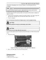
Page 63: ...ace of the glass Inspect the glass flat after cleaning to ensure all dust and residue has been removed 2 Close the transport 6 4 1 Removing the Glass Flat for Replacement or for Cleaning Both Sides CAUTION Handle the glass flat by its edge to avoid smudges and scratches CAUTION Do not twist or turn the glass flat while removing it To remove the glass flat from the scanner and clean both sides of i...

Page 64: ...e the tip where it still touches the scanner 5 Check the glass flat for chips and scratches NOTE If the glass flat is chipped or scratched replacement flats are available for purchase individually Part S001200A and as part of the Spectrum All In One Kit Part S005200 through Böwe Bell Howell Authorized Service Providers ASPs Consumable Parts Resellers CPRs and at www bbhscanners com For a complete ...

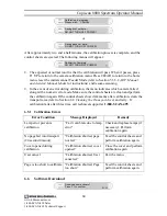
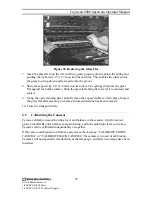
Page 65: ...y clean the exposed surface of the glass Inspect the glass flat after cleaning to ensure all dust and residue has been removed 10 Close the transport firmly 6 5 Calibrating the Cameras Camera calibration resets the white level and balance in the scanner It performs red green blue RGB color balance and gain setting and horizontal light level correction Cameras can be calibrated independently or tog...

Page 66: ...hich camera needs to be calibrated During the first 40 minutes of scanner operation the following menu will prompt you to wait until the scanner and lamps are fully warmed up before calibrating Wait OK CALIBRATE XX min for warm up 4 Press F1 OK to cancel the calibration and return to the previous menu Press F3 CALIBRATE to ignore the warm up requirement and proceed with calibration CAUTION Ignorin...

Page 67: ...e clean and perform the calibration again If the control sheets show dark marks after calibration clean the transport area refer to Section 6 8 Cleaning the Transport Area and retry If calibration fails after three tries call technical support at 1 800 SCAN 495 6 5 1 Calibration Errors Error Condition Message Displayed Remedy Lamp error prevents calibration Can t calibrate due to lamp error Check ...

Page 68: ...r rollers become dirty they may begin to slip on the paper or cause multi feeds To prevent feeding problems clean the skimmer rollers once a day or as needed NOTE Types and condition of the documents being scanned may require more frequent cleanings Take the following steps to clean the skimmer rollers 1 Remove all documents from the feeder and exit tray 2 Using the front panel buttons press the C...

Page 69: ...it tray 11 Repeat step 8 two to three times 12 Press the STOP key and then the CLEAR key 13 Discard the used skimmer cleaning sheet 6 8 Cleaning the Transport Area As the transport assembly components become dirty they may feed documents erratically or skew the documents as they enter the scanner To prevent erratic feeding clean the transport section about once a week or as needed Take the followi...

Page 70: ...n the page sensors once a week or as needed Take the following steps to clean the page sensors 1 Turn OFF the scanner 2 Remove any documents in the exit tray 3 Open the transport with the lift handle on the lower right side of the control panel opening as high as it will rise CAUTION Do not touch the page sensors with cotton swabs or anything else when cleaning them Use the transport cleaner only ...

Page 71: ...small particles of paper may build up on the sensor causing the feeder table not to drop after the last page is fed Cleaning the feeder sensor once per week or as needed will reduce this problem Take the following steps to clean the feeder sensor 1 Remove all paper from the feeder 2 Using the sensor and transport cleaner spray a short burst of air onto the sensor 64 www bbhscanners com 1 800 SCAN ...

Page 72: ...mp level Low back lamp level Lamps are available for purchase individually Part S004868 and as part of the Spectrum All In One Kit Part S005200 through Böwe Bell Howell Authorized Service Providers ASPs Consumable Parts Resellers CPRs and at www bbhscanners com For a complete listing of ASPs and CPRs please visit our website at www bbhscanners com The simplex scanner has two individual lamps and t...

Page 73: ...rd you 5 Pull each lamp out carefully 6 After the lamps are cool use an optic cleaning pad to wipe the lamps until they are free of dust 7 Insert both lamps back into the housing 8 Slide the lamp housing back in to the side frame of the scanner until it stops 9 Repeat steps 4 6 to remove and clean the back lamps NOTE If after cleaning the lamps do not operate or the light source is still degraded ...

Page 74: ...ket 4 Insert both lamps back in to the housing 5 Slide the lamp housing back in to the side frame of the scanner until it stops 6 Close the side access panel and the transport 7 Turn on the scanner 8 From the home menu press the LEFT arrow key until you reach the lamp replacement menu Lamp Replacement FRONT BACK 9 If you replaced the front lamps only or both the front and back lamps press F1 FRONT...

Page 75: ...immer Assembly The skimmer assembly is comprised of two rollers housed in a molded body Even thought the rollers last up to 600 000 scans each they will wear out over time which may result in document slippage or multifeeding Therefore the rollers are considered a consumable item and are available for purchase individually Part S004821 and as part of the Spectrum All In One Kit Part S005200 Skimme...

Page 76: ...y pull the skimmer assembly down and through the feeder 7 Release the spring loaded green lever back to its original position To replace the skimmer assembly take following steps 1 Turn off the scanner 2 Open the transport 3 Raise the manual autofeed lever on the feeder to the M position 4 Using your left hand pull the spring loaded green lever toward the left Secure it behind the lock pin 5 Inser...

Page 77: ... manual autofeed lever on the feeder to the A position 11 Clean the skimmer rollers as described in Section 6 7 Cleaning the Skimmer Rollers 6 13 Replacing the Feeder Skimmer Assembly Rollers NOTE If the skimmer housing is damaged replace the entire skimmer assembly and skimmer flag Refer to Section 6 12 Removing and Replacing the Skimmer Assembly for instructions NOTE This procedure is the same f...

Page 78: ...ocated on top of the assembly together and pull the cover off the assembly Figure 41 Lifting the Rollers From of the Skimmer Assembly 3 Lift the rollers up and out of the skimmer assembly 4 Pull the roller shaft from the roller assembly It should slide out easily Discard old rollers 71 www bbhscanners com 1 800 SCAN 494 Sales 1 800 SCAN 495 Technical Support ...

Page 79: ...moving and Replacing the Skimmer Assembly 6 14 Replacing the Feeder Separator Roller Sleeve Assembly The separator roller sleeve assembly is comprised of a separator roller sleeve also known as just the separator roller a brake assembly spacers and retaining o rings Even though the separator roller lasts up to 600 000 scans it will wear out which may result in document slippage and or multifeeding...

Page 80: ...f the scanner 2 Open the transport 3 Remove the skimmer assembly as indicated in Section 6 12 Removing and Replacing the Skimmer Assembly Figure 44 Separator Roller and Access Door The table below provides a legend for the above figure 1 Separator Roller Assembly 2 Separator Roller Access Door 4 Raise the manual autofeed lever on the feeder the M position 5 Open the separator access door As the do...

Page 81: ...fully place the separator roller assembly into the separator cradle The separator assembly can only be replaced in one direction One end of the separator assembly is keyed flat edge on the shaft The keyed end should be on the right side of the scanner when being inserted back into the scanner 15 Once the separator roller is placed back in the scanner push down on it lightly to ensure it is located...

Page 82: ...ller sleeve from side to side using Optic Cleaning Pad S003389 This removes any remaining oil film from the roller surface 4 Reinstall separator roller as indicated in Section 6 14 Replacing the Feeder Separator Roller Sleeve Assembly following steps 12 to 18 6 16 Imprinter Maintenance The following subsections explain how to maintain the imprinter on your scanner 6 16 1 Removing the Print Cartrid...

Page 83: ...on 6 15 4 Priming the Print Cartridge 6 16 3 Replacing the Print Cartridge To replace the print cartridge follow the steps below 1 Remove the empty print cartridge refer to Section 6 15 1 Removing the Print Cartridge CAUTION Do not touch the foil on the bottom of the new print cartridge with your fingers 2 Remove the new print cartridge from the box and inner container 3 Prime the new cartridge re...

Page 84: ...tridge if it has not been used for a few hours and pre firing the print cartridge did not fix the problem 3 Insert a paper clip into the cartridge as shown in the figure below Figure 47 Priming the Print Cartridge 4 Gently press on the cartridge bladder until a small amount of ink covers the foil 5 Remove the paper clip and allow the excess ink to return to the cartridge 6 Using a tissue gently re...

Page 85: ...t Cartridge To get optimal use out of your imprinter the print cartridge should be removed from the imprinter and stored if it has not been used for more than one hour A plastic storage container has been provided for this purpose CAUTION Make sure that the storage container lid is secured during storage 78 www bbhscanners com 1 800 SCAN 494 Sales 1 800 SCAN 495 Technical Support ...
Page 86: ... sensors Section 6 9 Entry exit sensor errors Page sensors need cleaning Clean the page sensors Section 6 9 Feeder elevator doesn t drop when out of paper Feeder sensor needs cleaning Clean the feeder sensor Section 6 10 Image too dark Lamps need to be replaced scanner will indicate Camera needs to be calibrated Replace the lamps Section 6 11 Calibrate the camera Section 6 5 Slippage of documents ...

Page 87: ...ror Bad missing frnt camera The EGSA reports that the front camera is not connected or not responding Please call technical support at 1 800 SCAN 495 Back Camera Error Bad missing back camera The EGSA reports that the back camera is not connected or not responding Duplex scanners only Please call technical support at 1 800 SCAN 495 Unknown Host Type Error Unknown EGSA host type The host type ID se...

Page 88: ...e allowable timeout period after power up Please call technical support at 1 800 SCAN 495 Feeder Error Bad missing feeder The feeder is not connected or is not responding Please call technical support at 1 800 SCAN 495 Illumination Errors Error Condition Message Displayed Explanation Remedy Front Lamps Low Error Low front lamp level The front lamp sensor indicates that front lamps are too low for ...

Page 89: ...ps if necessary Section 6 11 Front Lamp Replacement Error Replace front lamps Front lamp hours counter indicates front lamps have reached end of life Back Lamp Replacement Error Replace back lamps Back lamp hours counter indicates front lamps have reached end of life Front Camera Calibration Error Calibrate front camera The hour counter indicates that the front camera needs to be calibrated Perfor...

Page 90: ...n Transport Error Paper Jam Transport paper jam The page took too long to pass between the entry and exit sensors Refer to Section 5 9 Clearing Scanner Document Jams Multifeed Error Notify Multifeed Stop Line 1 Multifeed To resume Line 2 Press CLEAR or MF Ignore Multiple pages entered the transport Refer to Section 5 7 Multifeed Detector Page Entry Sensory Error Bad page entry sensor The entry sen...

Page 91: ... hole size setting to reject holes in pages and ragged page edges Section 5 3 3 4 Setting Up the Sensors for Hole Punched Paper Clean page entry sensors Section 6 9 Cleaning the Page Sensors If the problem persists please call technical support at 1 800 SCAN 495 User Actions Error Condition Message Displayed Explanation Remedy Stop Key Error Scanner Stopped User pressed the STOP key on the front p...

Page 92: ...xceeded the manufacturer s recommendations Replace the print cartridge Section 6 15 3 Front Print Head Error Bad front print head The host attempted to use the front imprinter but no front print head is detected Either the imprinter cartridge is not installed or not installed correctly Remove and reinstall imprinter cartridge Back Print Head Error Bad back print head The host attempted to use the ...

Page 93: ...E yyy Machine control software has executed an unexpected line of code Report displayed file name and line number to technical support at 1 800 SCAN 495 EGSA Communication Error EGSA serial comm error Serial communication error occurred between the scanner controller and EGSA Press CLEAR and continue scanning If error persists please call technical support at 1 800 SCAN 495 NOTE If any errors pers...

Page 94: ...he feeder that raises the top of the stack of documents to the correct height for proper feeding After the last document has been fed from the tray the tray in ADF mode drops to permit loading another stack of documents Error message A message displayed on the control panels These messages appear whenever the scanner determines that a problem exists Exit tray The output tray of the scanner As the ...

Page 95: ...urved path taken by a document as it passes through the scanner Paper transport The mechanical system for moving a document through the scanner Power cord The cord that connects the scanner to AC power Power cord receptacle The connector at the rear of the scanner into which the power cord is inserted The other end of the power cord is plugged into the wall outlet or other source of AC power Power...

Page 96: ...plex scanner A scanner designed to scan a single side of a document as it passes through the scanner Skew The result of feeding a document at an angle It looks crooked on the display and also looks this way when printed To minimize skew guide the document against the left document feed guide Skimmer module The skimmer module is comprised of a skimmer body that is attached to the rear feed rollers ...

Reviews: