3-5
Chapter 3: Operation
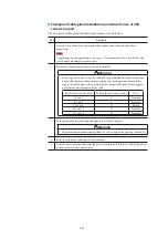
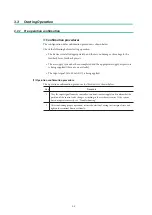
3.1.2 Auto-setup operation
Step
Procedure
1
Set the input signal to the device to 18 ±1 mA DC.
2
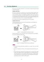
Using a flat-blade screwdriver, turn the external zero/span adjustment screw in the upper
part of the case 90° clockwise (counter-clockwise for Azbil Corporation’s VR and RSA
actuators for VFR type control valves), and hold that position for three seconds. If the
valve then starts to move in the direction that releases actuator air pressure, the auto-
setup process has begun, so remove the screwdriver.
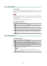
3
The valve alternates between fully closed and fully open two times. It then moves to the
vicinity of the 50 % open position. This takes approximately 3 to 4 minutes.
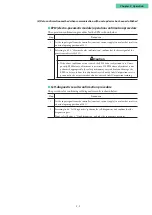
4
When the input signal becomes able to control the valve, the auto-setup operation ends.
After the operation ends, hold the input signal at 4 mA or higher for 30 seconds so that
the settings are written to non-volatile memory.
Note
•
While auto setup is running, do not set the input signal below 4 mA. (As long as the
signal is in the 4 to 20 mA range, changing it will not cause any problems.)
•
Do not use a magnetic screwdriver, as this may prevent the function from operating.
•
After the operation has completed, vary the input signal and confirm that the cor-
responding position results. If the span position has shifted, adjust the span. (See 3.2,
“External zero/span adjustment.”)
•
In some cases, configuration may not succeed due to the actuator’s diaphragm capac-
ity (if lower than with Azbil Corporation’s HA1 type actuator, which has a diaphragm
capacity of 850 cm
3
) or operation stroke (if less than 14.3 mm). If this occurs, refer to
4.4.4, “Control parameter configuration,” and manually adjust the dynamic character-
istics.
•
Even if actuator size or valve size is the same, depending on the combination of de-
vices, the default settings at the time of factory shipment are not always the same.
Check how the device operates after installation and adjust the settings if necessary.
•
After executing auto-setup, the forced fully open setting (see 4.4.7, “Forced fully
open/closed setting,”) may be changed. If necessary, reconfigure the forced fully open
value.
•
When an Azbil Corporation VFR type control valve is configured by turning the ex-
ternal zero/span adjustment switch in the counter-clockwise (DOWN) direction, the
actuator size is set to PARAM7-9, and the feedback lever is set to 0 % upward travel
and 100 % downward travel.
•
If the booster relay is incorporated, there is a possibility of hunting during auto-setup,
so either adjust the booster’s sensitivity or refer to 4.4.4, “Control parameter configu-
ration,” and manually adjust the dynamic characteristics.
•
If a speed controller is incorporated, set it to full open and execute auto-setup. Then,
adjust the speed with the speed controller.
•
If the device is purchased separately, its initial settings are set to those in the list of de-
fault values in 5.7, “List of Default Internal Data Values.” Because the default actuator
direction is reverse, the device will not work as is if mounted on the direct actuator.
Before operation, be sure to execute auto-setup and be sure that the device is config-
ured appropriately.
Summary of Contents for AVP200
Page 30: ......
Page 66: ...2 28...
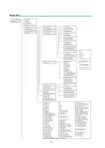
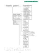
Page 80: ...4 4 Menu Tree...
Page 120: ...5 16...
Page 128: ...6 8 For models those date of manufacture are before September 2017...
Page 130: ...6 10 For models those date of manufacture are before September 2017...
Page 132: ...6 12 For models those date of manufacture are before September 2017...
Page 136: ...6 16 For models those date of manufacture are after October 2017...
Page 138: ...6 18 For models those date of manufacture are after October 2017...
Page 184: ...Appendix A Specifications A 25...
Page 185: ......
Page 188: ......
Page 190: ......

