2-16
2.2.6 Cables (for input signal or travel transmission)
■
Cable selection and conditions
The selection of and conditions related to cables for wiring are described below.
•
We recommend the use of CVV (JIS C 3401) 600 V control wires with PVC insulation
and a conductor cross-section of 1.25 mm
2
, or stranded cables with the same or better
performance specifications.
•
For locations that are readily affected by electromagnetic noise, use CVVS (JCS 4258)
shielded wires and metal conduits.
•
Select a sheath material that can withstand the cable installation environment (e.g.,
ambient temperature, corrosive gases, and corrosive liquids).
•
Pull the cable to the terminal box through the conduit connection port (G1/2 internal
thread, 1/2NPT internal thread, or M20×1.5 internal thread).
•
Use cable with an outer diameter between 7 and 12 mm. If a flameproof cable gland is
used, be sure to use packing that conforms to the outer diameter of the cable.
•
For wire ends, we recommend the use of crimp terminals (for M4 screws) with an
insulating sleeve.
•
The maximum cable length is 1500 m.
•
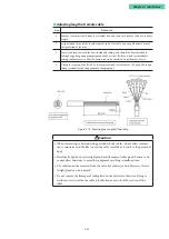
Use the appropriate remote cable for the wiring between the main unit and the valve
travel detector of the remote type (model AVP200/201).
■
Cabling
When cabling between the device and the controller, be careful of the following items.
•
When wiring, avoid sources of electromagnetic noise such as high-capacity trans-
formers, motors, and motive power supplies. Also, do not place cables in the same
tray or duct with power cables.
•
For waterproofing and wire damage prevention, we recommend using conduits and
ducts. In addition, be sure to use waterproof adapters at conduit connections.
•
In locations that are readily affected by electromagnetic noise, use conduits and ducts.
•
If shielded cables are used for wiring, as a rule ground one point on the distributed
control system side.
Note
•
The devices are intended for use in industrial locations defined in CE marking di-
rective (EN 61326-1).
•
A 3.5 % variation in the opening of the valve may occur around 2–4 MHz of con-
ducted disturbances, induced by radio-frequency fields (EN 61000-4-6).
•
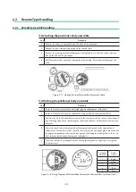
Use the provided remote cables as the cables between the main unit and the valve
travel detector of a remote type (Model AVP200/201). Regarding construction and
cabling, see 2.3, “Remote Type Handling.”
Summary of Contents for AVP200
Page 30: ......
Page 66: ...2 28...
Page 80: ...4 4 Menu Tree...
Page 120: ...5 16...
Page 128: ...6 8 For models those date of manufacture are before September 2017...
Page 130: ...6 10 For models those date of manufacture are before September 2017...
Page 132: ...6 12 For models those date of manufacture are before September 2017...
Page 136: ...6 16 For models those date of manufacture are after October 2017...
Page 138: ...6 18 For models those date of manufacture are after October 2017...
Page 184: ...Appendix A Specifications A 25...
Page 185: ......
Page 188: ......
Page 190: ......

