


Introduction
xvii
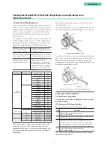
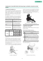
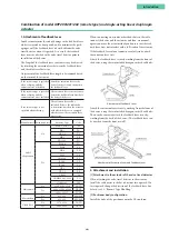
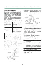
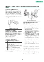
Adjustment of Attachment Positions
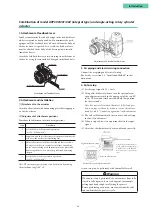
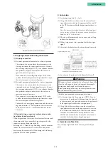
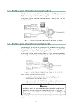
3. Air piping and electric wiring connection
[1] Air piping connection
(1) If control operation of control valve is direct operation
This refers to the state in which the valve moves in the
closing direction as the input signal increases. Connect
the reversing relay output OUT1 to the cylinder chamber
that performs output in order to close the valve in re-
sponse to increased pressure.
Next, connect the reversing relay output OUT2 to the
cylinder chamber that performs output in order to open
the valve in response to increased pressure.
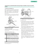
(2) If control operation of control valve is reverse operation
This refers to the state in which the valve moves in the
opening direction as the input signal increases. Connect
the reversing relay output OUT2 to the cylinder chamber
that performs output in order to close the valve in re-
sponse to increased pressure.
Next, connect the reversing relay output OUT1 to the
cylinder chamber that performs output in order to open
the valve in response to increased pressure.
For details, see on air piping connection and electric wir-
ing connection in 1.3, “Description of Device Structure
and Functions,” and 2.2, “Installation Method,” in this
document.
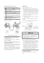
[2] Electrical wiring connection (cables between valve
travel detector and positioner)
When shipped from the factory, the valve travel detector and
the positioner body are normally shipped separated at the
connector unit on the positioner body.
Referring to 2.3, “Remote Type Handling,” in this document,
connect the valve travel detector cable to the body of the
device using the remote cable. When laying cable, follow ap-
propriate electrical work guidelines.
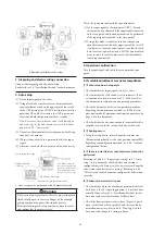
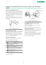
4. Auto-setup
(1) Set the input signal to 18 ± 1 mA.
(2) Using a flat-blade screwdriver, turn the external zero/
span adjustment switch in the upper part of the case 90°
in the UP direction, and hold that position for three sec-
onds.
Note: For reverse close (when the valve's fully closed posi-
tion is on top), set the valve action to reverse close before-
hand. See 4.4.3, “Valve system.”
(3) The valve will automatically start to move, and will stop
in about 3 to 4 minutes.
(4) When it stops, move it to a position that fits the input
signal.
(5) After that, check whether it has been adjusted correctly.
• Auto-setup can be performed with CommStaff as well.
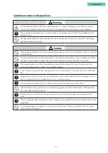
Warning
When auto-setup is performed, the valve moves from fully
closed to fully open, so there is a danger of, for example,
getting your hand caught or affecting the process.
Before performing auto-setup, move away from the valve,
and confirm that the process is safe.
Check the span point and perform span adjustment.
(1) Set the input signal to the span point (URV). (Zero ad-
justment can be performed if the input signal is adjusted
to the zero point, and span adjustment can be performed
if the input signal is adjusted to the span point.)
(2) Using a flat-blade screwdriver, turn the external zero
span adjustment switch on the upper part of the case in
the UP direction (clockwise) to cause the valve to move
such that the feedback lever rises upward, or turn it
DOWN (counterclockwise) to cause the valve to move
such that the feedback lever drops downward.
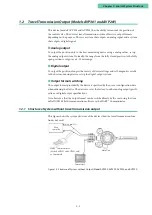
5. Operation confirmation
Vary the input signal, and check the zero point and span
point.
Note: When closing the
valve of the single-acting
type device with the lever
in the upward direction,
first set it to reverse close.
If performing auto-setup
External zero/span adjustment switch
Rotate in UP direction
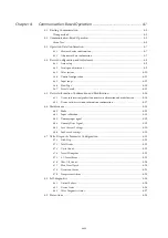
Summary of Contents for AVP200
Page 30: ......
Page 66: ...2 28...
Page 80: ...4 4 Menu Tree...
Page 120: ...5 16...
Page 128: ...6 8 For models those date of manufacture are before September 2017...
Page 130: ...6 10 For models those date of manufacture are before September 2017...
Page 132: ...6 12 For models those date of manufacture are before September 2017...
Page 136: ...6 16 For models those date of manufacture are after October 2017...
Page 138: ...6 18 For models those date of manufacture are after October 2017...
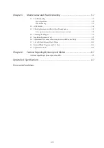
Page 184: ...Appendix A Specifications A 25...
Page 185: ......
Page 188: ......
Page 190: ......


