2-24
■
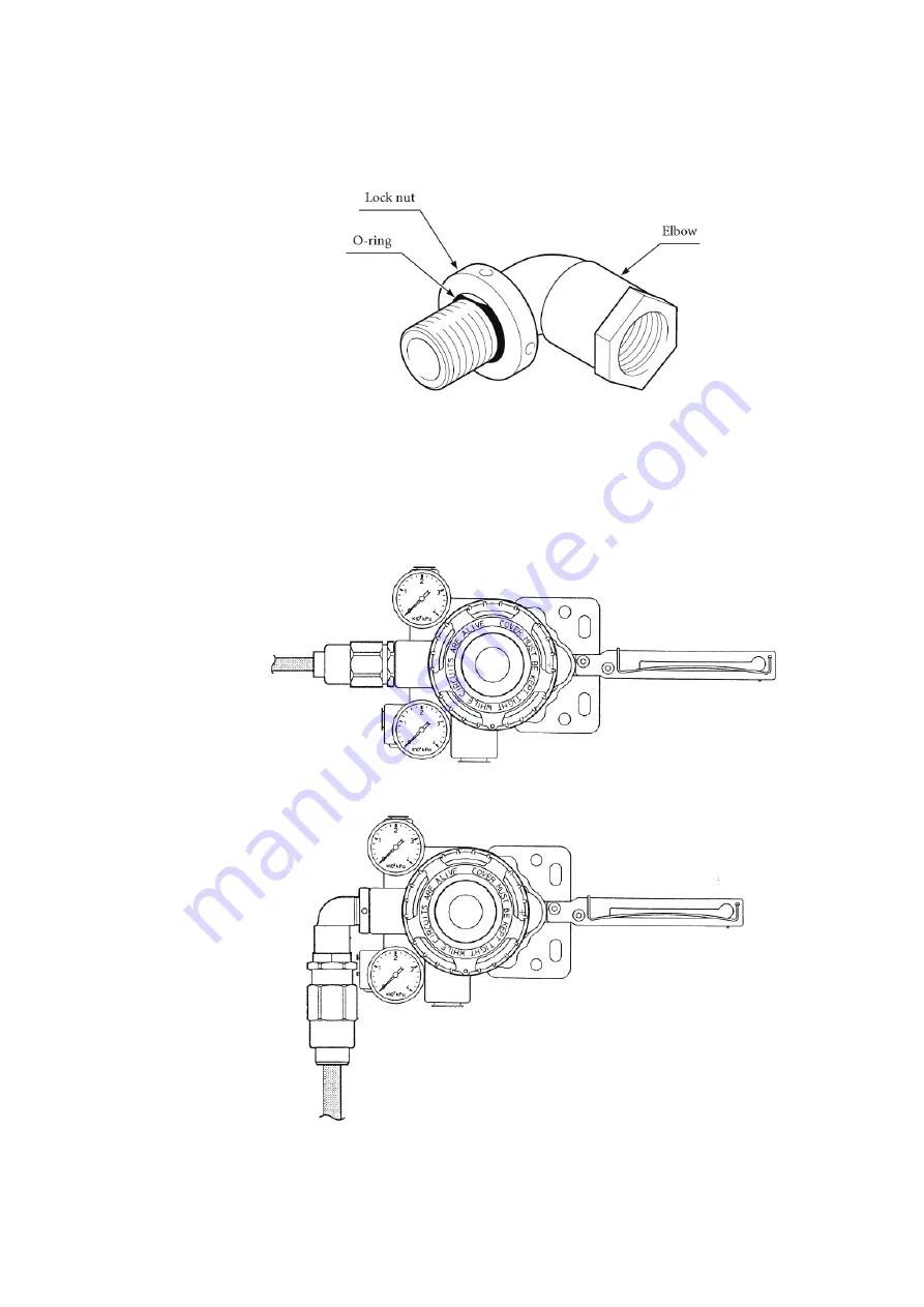
Structure of explosion-proof universal elbow
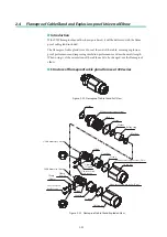
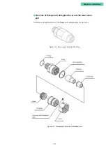
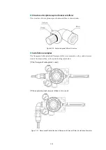
The structure of the explosion-proof universal elbow is shown below.
Figure 2-26. Explosion-proof Elbow Structure
■
Installation examples
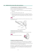
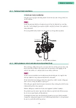
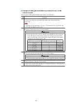
The flameproof cable gland and flameproof elbow are mounted on the conduit connec-
tion of the terminal box, as shown in the diagrams below.
[If the flameproof cable gland is used]
[If the explosion-proof universal elbow is also used]
Figure 2-27. Flameproof Cable Gland and Flameproof Universal Elbow Installation Examples
Summary of Contents for AVP200
Page 30: ......
Page 66: ...2 28...
Page 80: ...4 4 Menu Tree...
Page 120: ...5 16...
Page 128: ...6 8 For models those date of manufacture are before September 2017...
Page 130: ...6 10 For models those date of manufacture are before September 2017...
Page 132: ...6 12 For models those date of manufacture are before September 2017...
Page 136: ...6 16 For models those date of manufacture are after October 2017...
Page 138: ...6 18 For models those date of manufacture are after October 2017...
Page 184: ...Appendix A Specifications A 25...
Page 185: ......
Page 188: ......
Page 190: ......

