


1-5
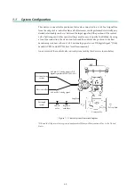
Chapter 1: Control System Structure
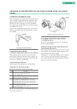
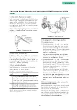
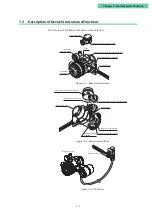
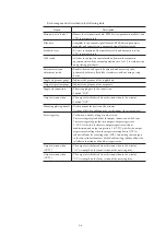
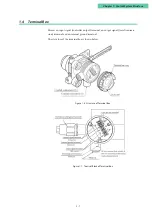
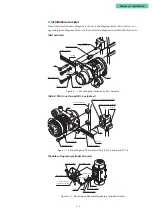
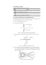
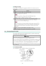
1.3 Description of Device Structure and Functions
The structure of the body of the device is shown below.
Pilot relay cover
Supply air connection
Output air connection
A/M switch
Supply air pressure gauge
External ground
terminal
Reversing relay supply air connection
Output air connection (OUT2)
Mounting plate (optional)
Feedback lever
Body
Terminal
box cover
Output air
pressure gauge
External zero/span adjustment switch
Output air connection (OUT1)
Reversing relay
Position detector
Positioner body
Figure 1-5-1. Body Structure (Front)
Figure 1-5-2. Body Structure (Rear)
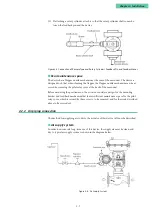
Figure 1-5-3. 200 Series
Summary of Contents for AVP200
Page 30: ......
Page 66: ...2 28...
Page 80: ...4 4 Menu Tree...
Page 120: ...5 16...
Page 128: ...6 8 For models those date of manufacture are before September 2017...
Page 130: ...6 10 For models those date of manufacture are before September 2017...
Page 132: ...6 12 For models those date of manufacture are before September 2017...
Page 136: ...6 16 For models those date of manufacture are after October 2017...
Page 138: ...6 18 For models those date of manufacture are after October 2017...
Page 184: ...Appendix A Specifications A 25...
Page 185: ......
Page 188: ......
Page 190: ......


