3-1
Chapter 3: Operation
■
Overview of this chapter
This chapter describes starting and stopping the device, as well as zero/span adjustment.
If you have purchased this device separately, be sure to read Chapter 2, “Installation,”
before reading this chapter.
Cautions to ensure safe operation
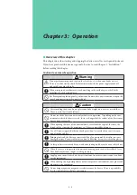
Warning
Do not perform wiring work, turn on the electricity, etc., when your hands are wet.
There is a risk of electric shock. Perform this work with the power supply turned off,
and with dry or gloved hands.
When wiring in a hazardous area, work according to the methods prescribed by the
guidelines for the hazardous area.
For flameproof explosion-proof specifications, do not under any circumstances open the
cover during operation (when powered up).
Caution
After installing the device, do not place your body weight on it, use it as a scaffold, etc.
There is a risk that it could fall over.
Do not touch the device unnecessarily while it is in operation. Depending on the envi-
ronment in which the device is used, there is a danger that the surface of the device may
be very hot or very cold.
When opening the cover of the terminal box, be careful of the edges of the cover, the
threads of the screws on the main unit, etc. There is a possibility of injury.
Use a DC power supply that has overload protection. An overload can cause the emis-
sion of smoke and fire.
Bringing tools and the like into contact with the glass portion of the display can cause
damage or injury. Exercise sufficient caution. In addition, be sure to wear safety glasses.
As this product is extremely heavy, watch your footing, and be sure to wear safety shoes.
When the device is in operation, do not touch moving parts such as the feedback lever.
Your hand may become caught, resulting in injury.
Supply power correctly based on the specifications. An incorrect power input can dam-
age the instrument.
When working in a high-temperature or low-temperature environment, wear gloves and
other protective equipment.
Do not bring magnets or magnetic screwdrivers near the device. There is a possibility
that the control valve will move in response.
Summary of Contents for AVP200
Page 30: ......
Page 66: ...2 28...
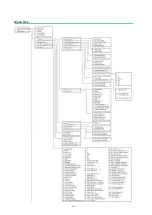
Page 80: ...4 4 Menu Tree...
Page 120: ...5 16...
Page 128: ...6 8 For models those date of manufacture are before September 2017...
Page 130: ...6 10 For models those date of manufacture are before September 2017...
Page 132: ...6 12 For models those date of manufacture are before September 2017...
Page 136: ...6 16 For models those date of manufacture are after October 2017...
Page 138: ...6 18 For models those date of manufacture are after October 2017...
Page 184: ...Appendix A Specifications A 25...
Page 185: ......
Page 188: ......
Page 190: ......

