Chapter 5: Maintenance and Troubleshooting
5-3
Troubleshooting
■
Introduction
Follow the procedures below to address any problems that occur during start-up or
during operation. If these troubleshooting procedures do not fix the problem, there is a
chance that the device is broken. Please use the contact information that appears on the
back cover of this manual.
■
The device does not operate (no output air pressure)
1. Check whether configuration was carried out correctly. (For example, check the
feedback lever allowable rotation angle.)
2. Check whether the appropriate supply air pressure is being supplied. (For example,
check whether there are any air leaks.)
3. Check whether the appropriate input signal (power supply) is being input. (For ex-
ample, check whether the electrical wiring is correct.)
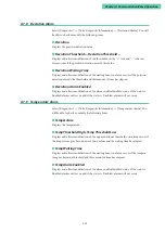
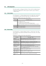
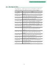
4. If communication with the actuator is possible, try the positioner's self-diagnostics
(section 4.8), and take measures based on the resulting messages.
5. Check whether there are any errors in the device's internal data settings.
■
Abnormal behavior of control valve (control valve not operating
properly despite output air being supplied)
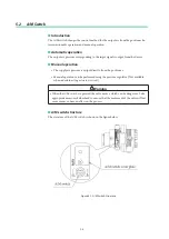
1. Change the A/M switch to the manual operating state, and then vary the regulator
valve and check whether the valve stem moves smoothly. (Check whether there is
galling or hardening of the valve packing.)
2. Check whether there are any errors in the device's internal data settings. (In particu-
lar, check actuator size, hysteresis, etc.)
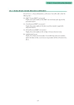
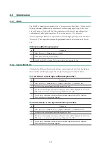
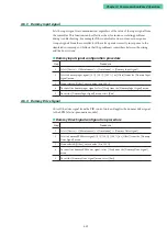
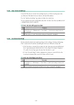
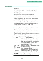
3. If any of the symptoms in the following table appear, take the indicated measures.
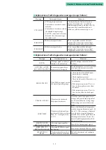
Problem
Checkpoints and Measures
Hunting occurs.
Overshoot occurs.
• Check whether the allowable rotation angle of the feedback lever is
being exceeded.
• Change the hysteresis setting from light to medium to heavy. If the
problem persists, leave the hysteresis setting at heavy and change the
actuator size setting to progressively smaller PRAM numbers.
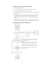
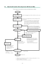
(For information regarding the procedure, see “Adjustment
procedure when hunting occurs” below.)
Full stroke does not
occur.
Response speed is too
slow.
• Check whether the valve fully closed position and fully open position
(zero/span) adjustment is correct.
• Check whether the EPM drive signals are within the 50 ±25 % range
(See 4.3.1, “Measured value confirmation.”)
Overshoot occurs at
startup
• When using a 3.85 mA min. signal, if the flow pressure fluctuates
greatly when the valve is fully closed, overshoot may occur at the
first startup. To suppress overshoot, temporarily lower the input
signal to 0 mA.
Slow response at
startup
• When starting from 0 mA, it may take some time until the travel
changes. After power is turned on, use a 3.85 mA or greater signal.
With this signal, response time will be normal.
Summary of Contents for AVP200
Page 30: ......
Page 66: ...2 28...
Page 80: ...4 4 Menu Tree...
Page 120: ...5 16...
Page 128: ...6 8 For models those date of manufacture are before September 2017...
Page 130: ...6 10 For models those date of manufacture are before September 2017...
Page 132: ...6 12 For models those date of manufacture are before September 2017...
Page 136: ...6 16 For models those date of manufacture are after October 2017...
Page 138: ...6 18 For models those date of manufacture are after October 2017...
Page 184: ...Appendix A Specifications A 25...
Page 185: ......
Page 188: ......
Page 190: ......

