


Introduction
xi
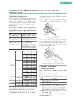
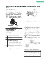
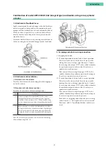
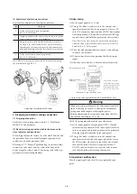
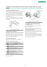
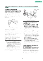
1. Attachment of feedback lever
In order to minimize the risk of damage to the feedback lever
while it is carried or transported, and to minimize the pack-
aging as well, the feedback lever is detached from the body of
the device when it is packed. As a result, the feedback lever
must be attached to the body of the device prior to installa-
tion of the device.
Attach the feedback lever securely, working from the front of
the device using the two included hexagon socket head bolts.
Attachment of Feedback Lever
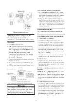
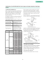
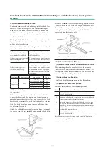
2. Attachment and installation
[1] Attachment to the actuator
Attach to the actuator with a mounting plate that is appropri-
ate for the actuator.
[2] Adjustment of attachment positions
Procedure for adjustment of attachment positions
Step
Procedure
1
Using for example the manual handle of the actuator
or manual operation via the external pressure regulator
with filter, set the position to 50 %. (With a double-acting
actuator, manual operation cannot be performed using the
A/M switch.)
2
Adjust the actuator such that the feedback lever reaches a
90° angle to the device's central vertical axis. Depending on
the actuator being used, adjustment may be performed by
moving the device, or it may be performed by moving the
pin.
Note: The accuracy specifications can be satisfied by making
the attachment angle 90° ± 2°.
Combination of model AVP300/301/302 (integral type) and double-acting rotary cylinder
actuator
Adjustment of Attachment Positions
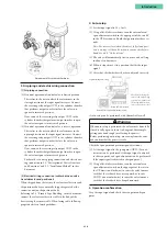
3. Air piping and electric wiring connection
•
Air piping connection
(1) If control operation of control valve is direct operation
This refers to the state in which the valve moves in the
closing direction as the input signal increases. Connect
the reversing relay output OUT1 to the cylinder chamber
that performs output in order to close the valve in re-
sponse to increased pressure.
Next, connect the reversing relay output OUT2 to the
cylinder chamber that performs output in order to open
the valve in response to increased pressure.
(2) If control operation of control valve is reverse operation
This refers to the state in which the valve moves in the
opening direction as the input signal increases. Connect
the reversing relay output OUT2 to the cylinder chamber
that performs output in order to close the valve in re-
sponse to increased pressure.
Next, connect the reversing relay output OUT1 to the
cylinder chamber that performs output in order to open
the valve in response to increased pressure.
For details, see air piping connection and electric wiring
connection in 1.3, “Description of Device Structure and
Functions,” and 2.2, “Installation Method,” in this docu-
ment.
Summary of Contents for AVP200
Page 30: ......
Page 66: ...2 28...
Page 80: ...4 4 Menu Tree...
Page 120: ...5 16...
Page 128: ...6 8 For models those date of manufacture are before September 2017...
Page 130: ...6 10 For models those date of manufacture are before September 2017...
Page 132: ...6 12 For models those date of manufacture are before September 2017...
Page 136: ...6 16 For models those date of manufacture are after October 2017...
Page 138: ...6 18 For models those date of manufacture are after October 2017...
Page 184: ...Appendix A Specifications A 25...
Page 185: ......
Page 188: ......
Page 190: ......


