141
2. Test the resistance between the two leads from the
sensor.
3. Compare the resistance reading to the Voltage/Resis-
tance Chart - Coolant Temperature in this section.
Air Temperature Sensor
NOTE: The component temperature must be
known before conducting this test. Allow the engine to
reach room temperature.
1. Disconnect the wiring harness from the air tempera-
ture sensor.
2. Test the sensor connector. Compare with the Volt-
age/Resistance Chart - Air Temperature in this sec-
tion.
NOTE: The air temperature sensor utilizes a therm-
istor. Resistance will change as temperature varies.
Testing Electric Oil Pump
(6000)
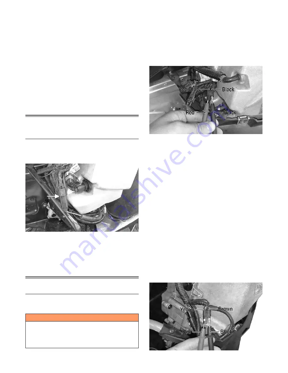
1. Remove the right-side access panel; then remove the
lower console from the skid plate. Disconnect the oil
pump connector.
CWI-109A
2. Set the selector to the OHMS position.
3. Test between the two terminals. Resistance must be
1.75-1.95 ohms.
NOTE: If replacing the oil pump, the A and B codes
must be entered using the CATT II Tool. The pump
must also be primed using the CATT II Tool.
Testing Voltage Regulator
NOTE: The following test should be made using a
Fluke Model 77 Multimeter.
6000
1. Remove the right-side access panel; then remove the
lower console from the right-side skid plate and
secure out of the way.
2. For the DC voltage test, connect the red meter lead to
the red/blue wire in the accessory connector; then
connect the black meter lead to the black wire in the
connector.
XM412A
3. Start the engine and allow it to idle. Meter reading
must be within 9-15 DC volts.
8000
1. Remove the both access panels and the hood; then
remove the harness wrap around the main harness
wires near the resonator.
2. Disconnect the three-wire connector securing the
main harness to the voltage regulator.
3. For the DC voltage test, connect the red meter lead to
the red/blue wire in the three-wire connector; then
connect the black meter lead to the brown wire in the
connector.
NOTE: Make sure that the test is being done on the
wires coming from the regulator and not the main
harness.
4. Start the engine and allow it to idle. Meter reading
must be within 9-15 DC volts.
5. For the AC voltage test, remove the lower console
from the right-side skid plate and secure out of the
way.
6. Connect the red meter lead to the yellow wire in the
connector; then connect the black meter lead to the
brown wire in the connector.
XM410A
! WARNING
Most voltages generated by the ignition system are suf-
ficient to interrupt pacemakers! All technicians, espe-
cially those using pacemakers, must avoid contact with
all electrical connections after the engine has been
started.
Summary of Contents for M 8000
Page 1: ...www arcticcat com SERVICE MANUAL www arcticcat com...
Page 42: ...41 500cc_2A_15...
Page 50: ...49 600_14_2...
Page 58: ...57 800_12_2...
Page 155: ...154 Troubleshooting Servomotor SERVO1A16...
Page 156: ...155 SERVO2rv16...
Page 193: ...192 0747 414 M 141 High Country Models...
Page 209: ...208 NOTES...
Page 210: ...Printed in U S A Trademarks of Arctic Cat Inc Thief River Falls MN 56701 p n 2260 847...


