135
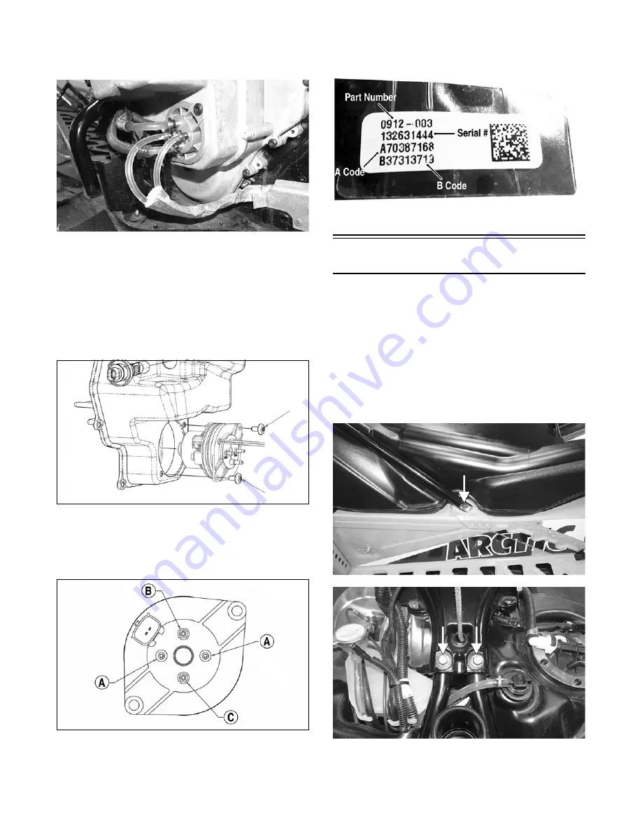
3. Remove all four hoses from the oil pump assembly;
then disconnect the oil pump harness and remove the
two screws securing the oil pump to the oil tank.
CWI-112
4. Carefully remove the oil pump from the oil tank.
NOTE: Do not disassemble the oil pump as it will
only be serviced as a assembly.
INSTALLING
1. Install the pump assembly into the oil tank and align
with the two mounting holes; then secure the pump
to the tank using the two screws (threads coated with
blue Loctite #243). Tighten to 60 in.-lb.
SNO-356
2. Install the two clear smaller hoses to the smaller
front and rear terminals (A); then install the hose
from the center cavity of the crankcase to the top ter-
minal (B). Install the hose from the fuel rail to the
lower terminal (C). Secure using the existing clamps.
SNO-355A
3. Secure the right-side skid plate using the existing
screw.
4. Bleed the oil-injection system using the CATT II
tool. Instructions included with the tool.
NOTE: If a new oil pump is being installed, be sure
to enter the A and B codes using the CATT II Tool.
SNO-1236A
Gas Tank
REMOVING
1. Remove the hood, access panels, and seat.
2. Remove the lower console.
3. Disconnect the reverse alarm; then remove the two
machine screws securing the upper console. Remove
the console.
4. Remove and retain all cap screws securing the rear
spar tubes to the chassis and steering support.
Account for inserts and nuts.
XM210A
XM212A
5. Disconnect the gasline hose, vent hose, and fuel
pump harness. Remove the gas tank.
Summary of Contents for M 8000
Page 1: ...www arcticcat com SERVICE MANUAL www arcticcat com...
Page 42: ...41 500cc_2A_15...
Page 50: ...49 600_14_2...
Page 58: ...57 800_12_2...
Page 155: ...154 Troubleshooting Servomotor SERVO1A16...
Page 156: ...155 SERVO2rv16...
Page 193: ...192 0747 414 M 141 High Country Models...
Page 209: ...208 NOTES...
Page 210: ...Printed in U S A Trademarks of Arctic Cat Inc Thief River Falls MN 56701 p n 2260 847...


