


Chapter 3 Software Navigation
Part Number: 0160-6411, Rev A, 02/2019
Page 127 of 314
Software Release: cOS 5.00
Lock Panel
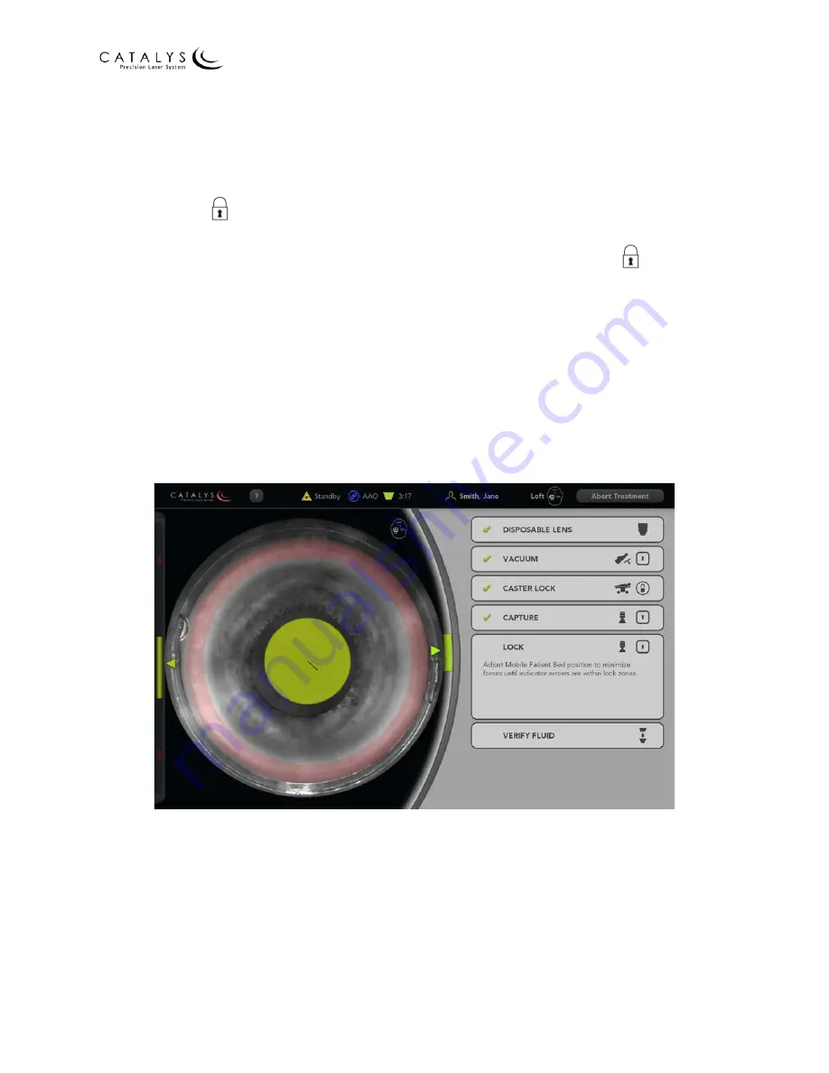
After the system verifies suction ring capture, the Lock panel opens. As instructed in the panel,
use the joystick control to adjust the bed/chair until all three indicators are within their
respective Lock Zones (i.e., the vertical green bar on the left, circular green area over the video,
and vertical green bar on the right). When all three indicators are within their respective Lock
Zones, press the
(Lock)
I
(on) button on the docking keypad.
NOTE
Alternatively, you can activate Guided Docking by pressing and holding the
(
Lock)
I
(on)
button. The system will adjust the bed/chair until all three indicators are within their respective
Lock Zones. Release the button after the lock engages or to stop the bed/chair at any point.
When the system detects that the lock has been secured, a check mark displays in the Lock
panel, and the lateral and vertical force indicators will minimize to the upper left corner of the
video for the rest of the treatment process.
The following sample screens show the suction ring/disposable lens assembly inside and outside
of the Lock Zones.
Figure 3.81 Docking Screen with Lock Panel Open—
Suction Ring/Disposable Lens Assembly Inside Lock Zone


