background image

8-14   |   3050 RM Moisture Analyzer

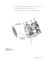
Analog Interface PCB

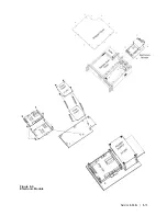
The Analog Interface PCB (AMETEK Part #591210901) is located on top of 
the MCU PCB at the front of the electronic module (Figure 8-9). 

Removing the analog interface PCB

•  Remove the four knurled screws that hold the board in place.

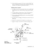
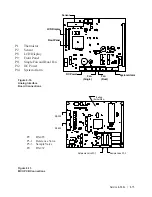
•  Unplug the connectors attached to the board (Figure 8-10).

•  Carefully, lift the board until it slides free of the connector.

Replacing the analog interface PCB 

•  Position the new analog interface PCB on the connector and press 

firmly to insert.

•  Replace the screws removed earlier. Do not overtighten.

•  Plug in the analog interface board connectors.

MCU PCB

The MCU PCB (AMETEK Part #59130901) is located below the Analog 
Interface PCB (Figure 8-6). 

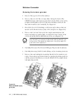
Removing the MCU PCB

•  Remove the analog interface PCB as described in the previous section.

•  Using a 1/16” hex wrench, remove the four standoffs that hold the 

MCU board in place. Unplug all connectors (Figure 8-11).

Replacing the MCU PCB

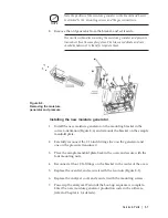
•  Install the new MCU PCB on the mounting plate using the four stand-

offs removed and a 1/16” hex wrench.

•  Remount the analog interface PCB as described in the previous sec-

tion. 

Summary of Contents for 3050-RM

Page 1: ...3050 RM Moisture Analyzer User Manual Process Instruments 455 Corporate Boulevard Newark DE 19702 PN 305892901 Rev R Configurator Version 3 0 ...

Page 2: ...ING USA Delaware 455 Corporate Blvd Newark DE 19702 Tel 302 456 4400 Fax 302 456 4444 USA Oklahoma 2001 N Indianwood Ave Broken Arrow OK 74012 Tel 918 250 7200 Fax 918 459 0165 USA Pennsylvania 150 Freeport Road Pittsburgh PA 15238 Tel 412 828 9040 Fax 412 826 0399 CANADA Alberta 2876 Sunridge Way N E Calgary AB T1Y 7H9 Tel 1 403 235 8400 Fax 1 403 248 3550 WORLDWIDE SALES AND SERVICE LOCATIONS US...

Page 3: ...ce Requirements 3 2 Utility Requirements 3 4 Electrical requirements 3 4 Sample Temperature and Pressure Requirements 3 4 Analyzer Installation 3 5 User Supplied Items 3 5 Rear Panel Connections and Interface Board 3 6 Installing the Dryer Figures 3 4a and b 3 8 Gas Connections Figure 3 5 3 10 Electrical Connections Figure 3 6 3 11 Voltage selection 3 11 Power connection 3 12 Communication Connect...

Page 4: ...ge C 5 4 Read Data F 5 4 Write Data H 5 5 Write Cell EEPROM L 5 5 Quit Q 5 5 Defined Responses slave to master 5 6 Simple Acknowledge 5 6 Acknowledge with Data 5 6 Failure 5 6 CHAPTER 6 3050 RM Configurator Software Setup 3050 RM Configurator Software 6 1 3050 RM Configurator Software Installation 6 1 Configuring the 3050 RM 6 2 General Tab 6 2 PC Communications 6 2 Saving Your Settings 6 3 Device...

Page 5: ...lection 6 10 CHAPTER 7 Troubleshooting Alarms 7 1 CHAPTER 8 Service and Parts Parts Replacement 8 1 Sensor 8 3 Removing the sensor 8 3 Installing the sensor 8 3 Mass Flow Meter 8 4 Removing the mass flow meter 8 4 Installing the mass flow meter 8 4 Moisture Generator 8 6 Removing the moisture generator 8 6 Installing the new moisture generator 8 7 Solenoid Valves 8 8 Removing the solenoids 8 8 Ins...

Page 6: ... module 8 12 Analog Interface PCB 8 14 Removing the analog interface PCB 8 14 Replacing the analog interface PCB 8 14 MCU PCB 8 14 Removing the MCU PCB 8 14 Replacing the MCU PCB 8 14 Reinstalling the Electronic Module 8 16 Board Connections 8 17 User Interface Board 8 17 Spare Parts 8 18 ...

Page 7: ...round checks Any use of the equipment in a manner not specified by the manufacturer may impair the safety protection originally provided by the equipment Grounding Instrument grounding is mandatory Performance specifications and safety protection are void if instrument is operated from an improperly grounded power source Verify ground continuity of all equipment before applying power NOTE Sample G...

Page 8: ... the environment and to conserve our natural resources AMETEK recommends that you arrange to recycle this prod uct when it reaches its end of life Waste Electrical and Electronic Equipment WEEE should never be disposed of in a munici pal waste system residential trash The Wheelie Bin marking on this product is a reminder to dispose of the product properly after it has completed its useful life and...

Page 9: ...s a technique allowing high frequency shield bonding while avoiding the AC ground metal connection In the case of shielded cables the drain wire or braid connection must be kept short A two inch connection distance between the shield s end and the nearest grounded chassis point ground bar or termi nal is highly recommended An even greater degree of shield performance can be achieved by using metal...

Page 10: ...losion Hazard Do Not Disconnect Equipment Unless Power Has Been Switched Off or the Area is Known to be Non Hazardous Risque d explosion Avant de déconnecter l équipement coupez le courant où vous assurez que l emplacement est designé non dangereux All input and output wiring must be in accordance with Class I Division 2 wiring methods NEC Sec 501 4 b or CEC 18 152 UL1604 CSA 213 and in accordance...

Page 11: ... xi ...

Page 12: ...ear on the documentation accompanying the equipment being returned declaring that the goods being returned for repair are American goods the name of the firm who purchased the goods and the shipment date The warranty shall not apply to any equipment or part thereof which has been tampered with or altered after leaving our control or which has been replaced by anyone except us or which has been sub...

Page 13: ... is 0 to 2500 PPMV The QCM sensor technology used in this analyzer is com patible with Air argon butane carbon dioxide ethane ethene Freon 12 Freon 22 Freon 32 Freon 114 Freon 116 Freon 125 Freon 134A Freon 152 helium hydrogren krypton natural gas neon nitrogen oxygen propane propene SF6 and xenon Carbon dioxide requires a custom sensor assembly Please contact the factory to confirm compatibility ...

Page 14: ...nal PC 4 line x 20 character LCD display that provides moisture data system operating parameters system messages and alarm conditions An 18 button keypad on the front of the unit that is used to set or change operating parameters and system values Serial interface to an external PC Contact Closure Signals The analyzer provides the following contact closure signals System Alarm Activates contact op...

Page 15: ...as flows through the sensor and a second measurement of the sensor frequency is recorded The difference between these two frequency measurements is known as the delta frequency ƒ The ƒ value is a function of the moisture concentration in the sample gas Gas Flow Sample system The 3050 RM Moisture Analyzer sample system enables the analyzer to make reliable water vapor measurements at concentrations...

Page 16: ... analyzer manifold The first is a simple bypass that allows for an increased flowrate of sample gas This means that when you open the bypass valve SV1 you reduce the time required to equilibrate all portions of the sample system that exist upstream of the bypass valve A capillary tube located immediately downstream of SV1 the coil shape in Figure 1 2 limits the flow rate to approximately 1 standar...

Page 17: ... valves SV2 SV3 SV4 are used to select the gas stream that is passed through the sensor the remaining two streams are passed to the vent In normal operation of the 3050 RM the analyzer continuously cycles between the sample and dry reference gas streams This switching action modulates the water vapor concentration to which the sensor is exposed As such the resonant frequency of the sensor crys tal...

Page 18: ...volumes and to stabilize flow To prevent false alarms from occurring during this time the display on the analyzer will read New Gas and the analyzer will automatically purge itself This purge period lasts for forty minutes During this period the Data Valid contact is opened and the flow alarms are suppressed You can abort this purge process by pressing the Verify key scrolling to Abort and then pr...

Page 19: ...t in ambiguous dew frost point values Calculation of Dewpoint Values for Hydrocarbon Streams The calculation of dewpoint values for hydrocarbon streams is covered by several standards Because there are differences between the dewpoint values calculated with the older North American standard ASTM D1142 which is based on the work published in IGT Research Bulletin 8 and the new European standard ISO...

Page 20: ...1 8 3050 RM Moisture Analyzer This page intentionally left blank ...

Page 21: ...pro pane propene SF6 and xenon Carbon dioxide requires a custom sensor assembly Contact the factory to confirm compatibility with other gases Read the Dryer Warning in the Special Warnings and Information section in the beginning of this manual for more information Range Calibrated range of 0 to 2500 PPMV Limit of Detection 0 1 PPMV nominal Accuracy 0 1 PPMV or 10 of reading whichever is greater R...

Page 22: ...One 4 to 20 mA DC analog output RS 232 RS 485 serial port Alarms Alerts Three independent contact closures of 30 VAC or 60 VDC maximum 10 VA or 1 A maximum resistive for system alarm moisture concentration alarm and data valid All are fail safe by default Alarms are available on RS 485 interface Environmental Conditions 5 C to 50 C 41 F to 122 F Optimal performance in low level applications is obt...

Page 23: ...Height 13 cm 5 25 inches Depth 42 cm 16 5 inches Net Weight 10 9 Kg 24 lb Approvals and Certifications MET Certified to UL CSA General Safety Requirements UL61010 CAN CSA C22 2 No 1010 1 Complies with UL1604 and CAN CSA C22 2 No 213 Class I Division 2 Groups A B C D T4 Electromagnetic Compatibility Directive EN61326 1 Industrial Low Voltage Directive EN61010 1 ...

Page 24: ...2 4 3050 RM Moisture Analyzer This page intentionally left blank ...

Page 25: ...use in Class 1 Division 2 Groups A through D or Non Hazardous locations only This chapter contains information on the installation and setup of the 3050 RM Moisture Analyzer including Analyzer Requirements Space Requirements Utility Requirements Electrical Requirements Sample Temperature and Pressure Requirements Installation Connections User Supplied Items Rear Panel Connections Dryer Installatio...

Page 26: ...lyzer requires an area 48 cm wide x 13 cm high x 42 cm deep 19 x 5 25 x 16 5 plus rear clearance for analyzer connec tions and proper ventilation Figures 3 1a b and c It should be located as close to the sample tap as possible Figures 3 1a and b Model 3050 RM dimensions front top and rear bottom ...

Page 27: ...Installation Start Up 3 3 Figures 3 1c Model 3050 RM dimensions top and sides ...

Page 28: ... supplied power cord s ter minated with a locally approved wall socket plug or the analyzer can be hardwired Sample Temperature and Pressure Requirements Inlet sample temperature 0 C to 100 C 32 F to 212 F Optimum input gas temperature 60 C 5 C 140 F 9 F For optimum performance sample line should be heat traced to main tain a constant sample temperature Minimum input pressure 138 kPa 20 PSIG Maxim...

Page 29: ...commended wire is 22 gauge twisted shielded pair External Sample Tubing Sample input tubing length should be as short as possible For optimum performance sample tubing should be thermally con trolled to maintain a constant sample input temperature Optimal results are obtained with the sample line maintained at 60 C Recommended sample gas input tubing is 1 8 inch OD electro polished 316L VAR stainl...

Page 30: ... Cable gland for signal connections 3 RS 232 Serial Port User serial communications interface Serial wiring supplied by user Observe caution regarding use in hazardous loca tions 4 Exhaust Fitting Vent port for cell exhaust 1 8 inch com pression fitting 5 Sample Inlet Fitting Input port for sample gas 1 8 inch com pression fitting 6 Power connector Connect hot 1 and neutral 2 to power connector an...

Page 31: ...yzer is the only analyzer on line or the last in a chain 12 RS 485 Serial Port User serial communications interface Serial wiring supplied by user 10 Analog Output 4 to 20 mA output to user recording equipment Wiring supplied by user 11 Alarm Contacts Connections for Data Valid Concentra tion Alarm and System Alarm Wiring supplied by user Figure 3 3 Model 3050 RM interface board connections ...

Page 32: ...e to avoid damage to the device 1 On the right side of the rear of the analyzer is the dryer acess com partment Figure 3 4 2 Loosen the four captured screws on the door of the compartment to remove the door 3 If you have a single dryer analyzer you must install the dryer in the bottom position An optional second dryer or contaminant trap is available If you have the two dryer or dryer trap version...

Page 33: ...both of the fittings and tighten the two VCR nuts over the fittings until they are finger tight 9 Tighten the nut an additional 1 8 turn If you have a two dryer or dryer trap version of the analyzer install the second dryer or trap in the upper position now following the same instructions 10 Replace the dryer compartment cover 11 The production codes for the dryers supplied with the analyzers have...

Page 34: ...a minute 1 Remove the Swagelok caps from the sample inlet fitting 6 and ex haust fitting 5 Keep the fitting caps If you have to ship the analyzer or if it has to be disconnected for an extended period of time reinstall the caps 2 Connect the sample input tube to the analyzer sample inlet 3 Connect the exhaust tube to the analyzer exhaust The exhaust must be vented to an appropriate vent system 4 C...

Page 35: ... switch the setting to 240 VAC or back to the 120 VAC setting follow the procedure below You must follow this procedure to prevent damage to malfunction of the analyzer 1 Ensure that the area is non hazardous and the analyzer has been de energized 2 Remove the terminal cover on back panel 3 Select 115 or 230 VAC on the voltage selector 10 located on the top left hand side of the user interface boa...

Page 36: ...ve the ground wire from the threaded chassis stud Figure 3 8 4 Loosen and remove the power cord strain relief cap with compression bushing 1 Figure 3 2 and pull out the power cord 5 Prepare the new power cord using the original cord as a guide remove outer jacket measure length of wires strip lengths of wires ring connector termination etc 6 Feed the strain relief cap with compression bushing onto...

Page 37: ...to the end of your cord 9 Replace rear cover 10 Reconnect power Communication Connections Figure 3 9 1 Disconnect the power from the analyzer and remove the rear panel terminal cover 2 Connect the 4 to 20 mA analog output 13 see Figures 3 10a and 3 10b and alarm and data valid terminals 14 on the interface board to the analyzer through the metallic signal conduit 2 Figure 3 2 Figure 3 8 Attach gro...

Page 38: ...connection analog output and alarm data valid contacts share the same cable RS 485 communications Turn on the RS 485 termination switch 11 Figure 3 9 if communi cating with one analyzer or the last in a chain of analyzers 2 wire and 4 wire mode selection is performed using software 4 Replace terminal cover NOTE ...

Page 39: ...Installation Start Up 3 15 Signal Connections 4 to 20 mA Figure 3 10b Externally powered 4 20 mA output connections Figure 3 10a Self powered 4 20 mA output connections ...

Page 40: ...us and system values VERIFY Used to define on demand verify settings and initiate a verify cycle ALARM Used to define alarm output settings ANALOG RANGE Used to scale the 4 to 20 mA output in pro portion to the moisture concentration TEST CONFIG Used to define device and communication settings Arrow Keys 2 4 6 8 Scroll up down left and right through menu items and system value lists Number Keys 0 ...

Page 41: ... Follow the instructions on the display Except where otherwise noted Press Enter Save changes and return to previous menu Press Cancel To exit without saving when entering data Any changes made will not be saved To go back through previous levels one level at a time until the display returns to the normal opera tion screen when browsing the menu list Overview of display The default display has fou...

Page 42: ...wn period Sample must be flowing during the dry down period You should allow 1 to 3 days for the analyzer to dry down and stabilize During this period the concentration value shown on the display and the data recorded from output should show a steadily decreasing trend System alarm messages may be displayed during this period When the dry down is complete the concentration value on the display sho...

Page 43: ...keypad Using a combination of the func tion keys numbers minus sign and decimal point you can set the param eters for your analyzer 5 7 ppmv Sampling High Concentration 5 0 ppmv Limit Line 1 Concentration Line 2 Status message Line 3 Alarm message Line 4 Alarm value Heartbeat Figure 4 1 Keypad and display for the 3050 RM Moisture Analyzer ...

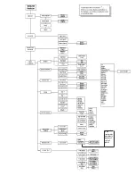
Page 44: ...4 2 3050 RM Moisture Analyzer Figure 4 2 Menu map for 3050 RM Moisture Analyzer ...

Page 45: ... to change during a verify Adjust Span Enable Select this function to adjust the span at the end of a verify cycle Disable Select this function if you do not want to adjust the span Verify This function initiates a verification cycle Abort This function aborts a verify cycle and returns the analyzer to normal operation Figure 4 3 Main menu for the Verify key VERIFY Hold Outputs Enable Disable Adju...

Page 46: ...e high limit value in moisture units selected Low Limit Enter the low limit value in moisture units selected Enable Alarm Select Enable or Disable to activate the moisture concentration alarm relay Figure 4 4 Main menu for Alarm key ALARM High Limit Low Limit Enable Alarm Enter Value Enter Value Enable Disable ...

Page 47: ...onal to the moisture readings Maximum Conc Enter the moisture reading equivalent to 20 mA Minimum Conc Enter the moisture reading equivalent to 4 mA Example To scale the analog output to represent a 0 to 100 PPMV range enter the following settings Maximum Conc 100 Minimum Conc 0 RANGE Maximum Conc Minimum Conc Enter Value Enter Value Figure 4 5 Main menu for Range key ...

Page 48: ...to 9 The default is 5 Back Light Select On or Off The default is ON Font This is a factory set parameter that identifies the type used for the display on the ana lyzer CONFIG Display Communication Sample Gas Clock Verify Schedule Production Codes Moisture Unit System Test Figure 4 6 Main menu for the Config key Config Display Contrast Back Light Font Enter Value 1 to 9 On Off Enter Value 0 or 1 ...

Page 49: ...0 is reserved see the Special Addresses section in Chapter 5 for details Baud Rate Select the baud rate at which you transfer data 9600 or 19200 The default is 9600 RS 485 Mode Optional Select 2 wire or 4 wire The default is 4 wire Config Communication Node Address Baud Rate RS 485 Mode optional Enter Address 9600 19200 Two Wire Four Wire ...

Page 50: ...e K factors and its value is defined as 1 000 To estimate the K factor for another gas take the ratio of the molar heat capacity constant pressure of nitrogen to that of the sample gas For example the K factor of argon would be estimated as follows Molar heat capacity of nitrogen 29 12 JK 1 mole 1 Molar heat capacity of argon 20 79 JK 1 mole 1 K factor 29 12 JK 1 mole 1 20 79 JK 1 mole 1 K factor ...

Page 51: ...yzer is greater than 1 SLPM This high sample flow rate helps to improve the response speed of the system The gas saver feature allows the user to control the state of the bypass valve so that the analyzer runs on a sample flow rate of 150 SCCM The operation of the valve can be controlled by checking the Gas Saver box to close the bypass valve or leaving it unchecked to leave the bypass valve open ...

Page 52: ...the day Day of the Week Select the day of the week from the list Month Enter the 2 digit value for the month Hour Enter the value using the 24 hour clock Minute Enter the 2 digit value for minutes Config Clock Year Day Day of Week Month Hour Minute Enter Value Enter Value Enter Value Enter Value Enter Value Sunday Monday Tuesday Wednesday Thursday Friday Saturday ...

Page 53: ... the starting hour Duration Enter the verify period value in minutes AMETEK recommends performing a verification cycle every week for the first month of operation After this start up period the analyzer will have dried down sufficiently to increase the verification interval to 1 month AMETEK recommends that the duration of the verifica tion cycle be set to 30 i e 30 minutes NOTE Config Verify Sche...

Page 54: ... number contains the dryer capacity value which is used to es timate the life expectancy of the device The options are single one dryer or double two dryers If you are using an analyzer equipped with a single dryer you will se lect Single and enter the Production Code If you are using an analyzer equipped with two dryers you will select Double and enter the Produc tion Code Use caution as entering...

Page 55: ... Units prompt displays the list If a dew frost point is selected you must enter a value for the process pressure in units of kPa If you change the moisture units remember to make the necessary changes to the Alarm and Analog Range settings PPMV Cen grade Fahrenheit Moisture Unit Select Unit Config Pressure KPa Pressure KPa lbs mmscf mg Nm3 ppm W ...

Page 56: ...se the System Test Key to perform tests on various components of the analyzer Test Display Tests the display by providing a checker board pattern on the display Test Keypad Tests the keypad by echoing characters to the display Test Alarms Tests the alarm contacts by toggling them open close Test Analog Output Tests the analog output by allowing the user to set outputs to 4 12 or 20 mA Test Serial ...

Page 57: ...is the character 3E The End Flag is a carriage return 0D The Node address is a two byte hexadecimal ASCII value in the range 00 through EF Addresses F0 through FF are reserved The command byte is a single ASCII character The Data field is of variable length and contains ASCII characters The checksum is a two byte ASCII hexadecimal field representing the modulo 256 sum of Node Address Command Byte ...

Page 58: ...essage format for slave responses containing a data field is seen in Figure 5 2 The message format for slave acknowledge without a data field is seen in Figure 5 3 The message format for slave failure response is seen in Figure 5 4 Figure 5 2 Slave response message format Figure 5 3 Message format for slave acknowledge Figure 5 4 Slave failure response format ...

Page 59: ...intended for use in configurations with a single slave The slave will respond to all messages with node address F0 You must be careful to prevent multiple slaves from receiving commands with the broadcast address as this will cause a bus contention Defined Commands master to slave There are a total of nine commands that can be issued from the master These are listed in the Figure 5 5 Figure 5 5 De...

Page 60: ... failure response Master 99BB4 CR Slave N01 CR Acknowledge C Requests a simple acknowledge from the slave Useful to determine if there is a device at that node address Master 99CB5 CR Slave A CR Read Data F The data field of this frame contains the handle for a system variable See Figures 5 7a and 5 7b for a list of defined handles for system variables Example Master 34F0512 CR Slave A1234540 CR S...

Page 61: ...7b for a list of defined handles for system variables Example Master 34H05123 40C CR Slave A CR Write Cell EEPROM L Copy cell serial number and cell calibration coefficients into cell EEPROM Example Master 34LB3 CR Slave A CR Quit Q Verify cycle is terminated immediately and normal operation resumed Example Master 34QB8 CR Slave A CR ...

Page 62: ...be returned a simple acknowledge consisting of an ASCII A will be sent Example Slave A CR Acknowledge with Data If a command issued by the master requires data in response an Acknowl edge with Data response will be issued This response consists of an ACSII A followed by data and checksum Example Slave A0123456A6 CR Failure All failure responses consist of an ASCII N followed by a two byte hexa dec...

Page 63: ...Serial Communications 5 7 Figure 5 6 Defined Failure Codes ...

Page 64: ...5 8 3050 RM Moisture Analyzer Figure 5 7a Variable Table ...

Page 65: ...Serial Communications 5 9 Figure 5 7b Variable Table ...

Page 66: ...5 10 3050 RM Moisture Analyzer This page intentionally left blank ...

Page 67: ...ation 1 Insert the configurator software CD into CD ROM drive 2 The installation program should begin to run immediately If it does not start automatically click RUN from the Windows Start menu Type the drive letter followed by a colon and a backslash and the word setup exe d setup exe and click OK to start the installation program 3 Follow the instructions on the subsequent screens to complete th...

Page 68: ...er and for PC communications Figure 6 1 After initial setup any changes to the analyzer communications pa rameters must be made using the Device Communications tab These changes must be made before you make any changes to the computer serial port settings PC Communications Click the Setup button to configure PC Communications The Serial Port Communication screen opens Figure 6 2 NOTE Figure 6 2 PC...

Page 69: ...s you have made click Cancel Device Refer to Figure 6 1 Name Type in a name for the analyzer Description Type in a description for the analyzer Save Configuration button Save the analyzer s internal parameters to a file The Save As dialog box opens so that you can name and save the file Restore Configuration button Restore the analyzer s internal parameters from a file The Open dialog box appears ...

Page 70: ... right hand corner Theanalyzer serial number and sensor serial number and the moisture generator and dryer codes are also displayed In the lower right hand corner above the Help button is the Configurator software version number Saving Your Settings To save settings on the General tab click Apply To save settings and exit the program click Apply Exit To abort changes you have made click Cancel Exi...

Page 71: ...ies the analyzer s address and the type of serial communication cable that is being used Address Type the network address for the analyzer being con nected Two Wire RS 485 Click if you are using a 2 wire cable Four Wire RS 485 Click if you are using a 4 wire cable Saving Your Settings To save settings on the Device Communications tab click Apply To save settings and exit the program click Apply Ex...

Page 72: ...low cycle time to maximize cell life Gas Saver check box Check to enable Gas Saver This feature allows you to minimize gas usage 4 20 mA Output Set up your analog output range 20 mA Enter your high analog output limit 4 mA Enter your low analog output limit Hold during Verify Check this box to hold analyzer output during verifica tion Alarm Output Set up the limits for the concentration alarm Enab...

Page 73: ...verify cycle Not checked The analyzer verifies only Set Clock Time Synchronization Click Set Clock to synchronize the clock within the analyzer with the PC The Time Synchronization box opens with the PC time and date and the analyzer time and date Click Synchronize to set the time or click Cancel to close the box Set Dryer Production Code Click to enter the Dryer Production Code for the dryer that...

Page 74: ...he Hour slot at the bottom of the box The analyzer uses a 24 hour clock Example 1 00 PM 13 hours Weekly Select the day of the week from the drop down list under Day of the week at the bottom of the box You must also enter a time of day 1 through 24 in the Hour slot to begin the verify Monthly Enter the numeric 1 through 28 day of the month in the Day slot and the time 1 through 24 in the Hour slot...

Page 75: ...e As screen opens so that you can browse to where you want to save the file The file format is Excel compatible CSV format Concentration readings data for the last 24 hours can be written to this file from the analyzer s data buffer Monitor Tab Use the Monitor tab to check on analyzer operation From this tab you can also collect data from the analyzer Figure 6 7 Status tab Figure 6 8 Monitor tab ...

Page 76: ...ess Save button The file format is csv which is Excel compatible All data displayed on the Monitor page will be stored in the specified file Off Data collection will terminate and the file will close when the Off button is pressed or another configurator tab is selected Rate The preferred data collection rate is 0 5 minutes and is set as the default A record is created every 30 seconds The collect...

Page 77: ...ting 7 1 TROUBLESHOOTING Alarms Following is a table of alarm messages Figure 7 1 for the AMETEK 3050 RM Moisture Analyzer If there is a problem the alarm will appear on the LCD screen on the third and fourth line ...

Page 78: ...7 2 3050 RM Moisture Analyzer This page intentionally left blank ...

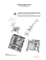
Page 79: ...Parts 8 1 Figure 8 1 Model 3050 RM exploded view CAUTION SERVICE AND PARTS Parts Replacement Make sure that power has been disconnected from the analyzer before attempting to remove or replace any of the parts ...

Page 80: ...8 2 3050 RM Moisture Analyzer Figure 8 3 Sensor removal in Model 3050 RM Figure 8 2 Sample System Model 3050 RM ...

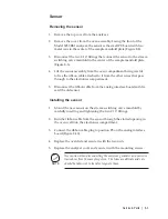
Page 81: ...h to the electronics compartment 5 Disconnect the ribbon cable from the analog interface board and dis card the old sensor Installing the sensor 1 Mount the new sensor on the stream switching valve manifold by carefully inserting and tightening the two 1 16 fittings 2 Run the ribbon cable from the sensor through the slotted opening in the oven wall into the electronics compartment 3 Connect the ri...

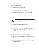
Page 82: ...tly lift the manifold out of the oven All of the wiring connections should still be intact at this time you will need to rest the sample manifold plate on top of the analyzer to remove the flow meter 5 Disconnect the cable from the flowmeter Figure 8 4 6 Disconnect the 1 16 inch tubing connections at both ends of the flow meter Figure 8 4 7 From the bottom side of the sample manifold plate remove ...

Page 83: ...ct all four 1 16 fittings on the bracket in the center of the oven 6 Replace the oven lid and secure it with the two nuts 7 Replace the analyzer cover and secure it with the mounting nuts Figure 8 4 Model 3050 RM Mass flow meter ...

Page 84: ...he sample manifold plate the square aluminum mounting plate located in the front section of the oven and gently lift the manifold out of the oven Figure 8 5 All of the wiring connections should still be intact at this time you will need to rest the sample manifold plate on top of the analyzer to perform the valve replacement 5 Carefully disconnect the 1 16 inch fitting on the pressure transducer 6...

Page 85: ...rrect orientation Figure 8 6 and remount the bracket on the sample manifold plate 2 Carefully reconnect the 1 16 inch fittings two on the generator and one on the pressure transducer 3 Place the sample manifold plate back in the oven and secure with the four mounting nuts 4 Reconnect all four 1 16 fittings on the bracket in the center of the oven 5 Replace the oven lid and secure it with the two n...

Page 86: ...the manifold out of the oven Figure 8 5 All of the wiring connections should still be intact at this time you will need to rest the sample manifold plate on top of the analyzer to perform the valve replacement 5 If you are replacing any of the three way solenoid valves disconnect the 1 16 inch fitting that connects the top port on the valve to the ex haust manifold Figure 8 7a and 8 7b If you are ...

Page 87: ...ure that both O ring seals are properly seated 2 If you are replacing one of the three way valves reconnect the 1 16 inch fitting to the appropriate port on the exhaust manifold 3 Place the sample manifold plate back in the oven and secure with the four mounting screws 4 Reconnect all four 1 16 fittings on the bracket in the center of the oven Figure 8 2 5 Replace the oven lid and secure it with t...

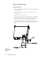
Page 88: ...he compartment cover 3 Remove the cover from the analyzer 4 The single dryer is located in the bottom position If your analyzer is equipped with two dryers or a dryer and a trap there will be a dryer in bottom position and a dryer or a trap in the top position 5 Loosen the 1 8 inch fittings on the dryer s trap and remove the dryer s trap from the analyzer Discard the used gaskets from the fit ting...

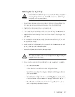
Page 89: ...have a second dryer or trap Repeat Steps 1 through 4 for the second dryer or trap 6 Place the dryer compartment cover onto the rear of the analyzer and secure with the four captured screws 7 Enter the production code for the new dryer The dryer production code is entered only once even if your analyzer is equipped with two dryers 8 Power up the analyzer Wait until the boot up sequence is complete ...

Page 90: ...re 8 9 as a reference for locating the items described in this proce dure Locate the four 4 Phillips head screws on the electronics module Using the appropriate tool remove the mounting hardware With all the interconnecting wiring and tubing still attached remove the electronic module from the 3050 RM assembly by pulling up and slightly towards the front of the analyzer Once you remove the electro...

Page 91: ...Service Parts 8 13 Figure 8 9 Electronic Module ...

Page 92: ... interface PCB on the connector and press firmly to insert Replace the screws removed earlier Do not overtighten Plug in the analog interface board connectors MCU PCB The MCU PCB AMETEK Part 59130901 is located below the Analog Interface PCB Figure 8 6 Removing the MCU PCB Remove the analog interface PCB as described in the previous section Using a 1 16 hex wrench remove the four standoffs that ho...

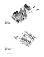
Page 93: ... Side RS 232 RS 485 Reference Valve P3 1 Sample Valve P3 3 P1 Thermistor P2 Sensor P8 LCD Display P9 Front Panel P11 Single Fan and Dual Fan P12 DC Power P14 System Alarm P2 RS 485 P3 1 Reference Valve P3 3 Sample Valve P4 RS 232 Figure 8 10 Analog Interface Board Connections Figure 8 11 MCU PCB Connections ...

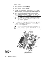
Page 94: ...onics module reassemble the analyzer 1 Carefully reposition the electronic module above and to the front of the analyzer Lower the module into the analyzer so the screws at the four corners can be attached 2 Attach the mounting plate of the electronic module to the analyzer as sembly using the four screws you removed earlier ...

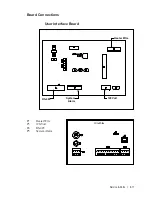
Page 95: ...Service Parts 8 17 Board Connections User Interface Board 120 Volt System Alarm RS 485 Heater Wire 120 Volt System Alarm RS 485 Circuit Side P1 Heater Wire P3 120 Volt P4 RS 485 P5 System Alarm ...

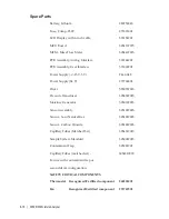
Page 96: ...24 V 271768001 Dryer 583072901S Pressure Transducer 305450901S Moisture Generator 305010901S Sensor Assembly 305122901S Sensor Sour Natural Gas 305122902S Sensor Carbon Dioxide 305122903S Capillary Tubes Matched Set 305431901S Sample System Manifold 305002901S Contaminant Trap 305921901 Capillary Tubes matched set 305431903S For use with contaminant trap or second dryer configuration SAFETY CRITIC...

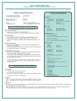
Page 97: ... at the source 3 Once the sample flow starts the analyzer will be in normal operating mode Allow analyzer to warm up for 45 minutes Dry Down Allow 1 to 3 days for the analyzer to dry down and stabilize At end of dry down period concentration value on display will be stable and recorded data will level off Verify Key Hold Outputs Enable or Disable Adjust Ofst Span Enable or Disable Verify Runs inte...

Page 98: ...PPmV Centigrade Fahrenheit lbs mnscf mg Nm3 ppmW ...

Reviews: