3-14 | 3050-RM Moisture Analyzer
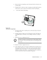
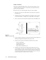
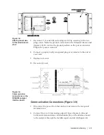
3. Connect the RS-232 or RS-485 serial communication to the analyzer.
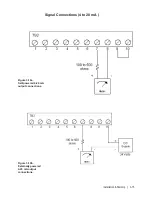
The RS-485 connection, analog output and alarm/data valid contacts
share the same cable.
RS-485 communications
-
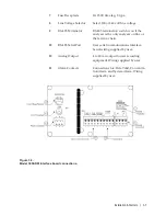
Turn on the RS-485 termination switch (11) Figure 3-9 if communi-
cating with one analyzer or the last in a chain of analyzers.
2-wire and 4-wire mode selection is performed using software.
4. Replace terminal cover.
NOTE
Summary of Contents for 3050-RM
Page 11: ... xi ...
Page 20: ...1 8 3050 RM Moisture Analyzer This page intentionally left blank ...
Page 24: ...2 4 3050 RM Moisture Analyzer This page intentionally left blank ...
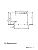
Page 27: ...Installation Start Up 3 3 Figures 3 1c Model 3050 RM dimensions top and sides ...
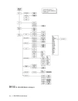
Page 44: ...4 2 3050 RM Moisture Analyzer Figure 4 2 Menu map for 3050 RM Moisture Analyzer ...
Page 63: ...Serial Communications 5 7 Figure 5 6 Defined Failure Codes ...
Page 64: ...5 8 3050 RM Moisture Analyzer Figure 5 7a Variable Table ...
Page 65: ...Serial Communications 5 9 Figure 5 7b Variable Table ...
Page 66: ...5 10 3050 RM Moisture Analyzer This page intentionally left blank ...
Page 78: ...7 2 3050 RM Moisture Analyzer This page intentionally left blank ...
Page 91: ...Service Parts 8 13 Figure 8 9 Electronic Module ...
Page 98: ...PPmV Centigrade Fahrenheit lbs mnscf mg Nm3 ppmW ...


