8-8 | 3050 RM Moisture Analyzer
Solenoid Valves
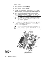
1. Remove the top cover from the analyzer.
2. Remove the cover for the oven assembly.
3. Disconnect the 1/16 inch fittings on all four sample tubes, which are
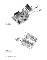
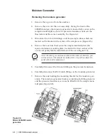
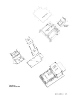
located on the bracket in the center of the sample oven (Figure 8-7a).
4. Remove the four nuts that secure the sample manifold plate (the
square aluminum mounting plate, located in the front section of the
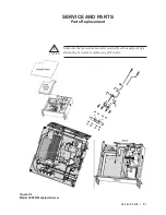
oven), and gently lift the manifold out of the oven (Figure 8-5).
All of the wiring connections should still be intact at this time; you
will need to rest the sample manifold plate on top of the analyzer to
perform the valve replacement.
5. If you are replacing any of the three-way solenoid valves, disconnect
the 1/16 inch fitting that connects the top port on the valve to the ex-
haust manifold (Figure 8-7a and 8-7b).
If you are removing the 3-way solenoid that is directly behind the fan,
you will need to remove the fan first (Figure 8-7a) so that you can ac-
cess the screws that hold the solenoid in place.
NOTE
NOTE
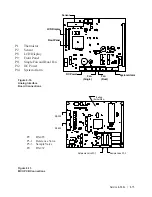
Figure 8-7a.
Model 3050 RM.
Solenoids.
Summary of Contents for 3050-RM
Page 11: ... xi ...
Page 20: ...1 8 3050 RM Moisture Analyzer This page intentionally left blank ...
Page 24: ...2 4 3050 RM Moisture Analyzer This page intentionally left blank ...
Page 27: ...Installation Start Up 3 3 Figures 3 1c Model 3050 RM dimensions top and sides ...
Page 44: ...4 2 3050 RM Moisture Analyzer Figure 4 2 Menu map for 3050 RM Moisture Analyzer ...
Page 63: ...Serial Communications 5 7 Figure 5 6 Defined Failure Codes ...
Page 64: ...5 8 3050 RM Moisture Analyzer Figure 5 7a Variable Table ...
Page 65: ...Serial Communications 5 9 Figure 5 7b Variable Table ...
Page 66: ...5 10 3050 RM Moisture Analyzer This page intentionally left blank ...
Page 78: ...7 2 3050 RM Moisture Analyzer This page intentionally left blank ...
Page 91: ...Service Parts 8 13 Figure 8 9 Electronic Module ...
Page 98: ...PPmV Centigrade Fahrenheit lbs mnscf mg Nm3 ppmW ...

