


20 Gear Drive, Plymouth Ind. Park, Terryville, CT 06786
Tel: (860) 585-1254 Fax: (860) 584-1973 http://www.amci.com
SV160E2 User Manual
I
NSTALLING
THE
SV160E2
83
1.7 Input Connector (continued)
1.7.1 Compatible Connectors and Cordsets
Many different connectors and cordsets are available on the market, all of which will work with the SV160E2
provided that the manufacturer follows the A-coded M12 standards. The following connector and cordset is
available from AMCI.
Table T1.2 Compatible Digital Input Connectors and Cordsets
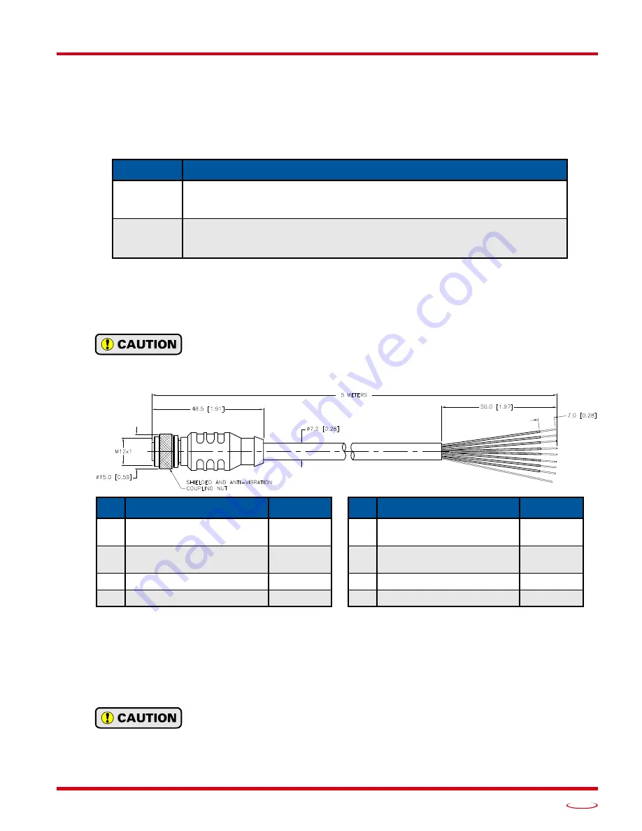
1.7.2 CNFL-5M Color Code and Shield Wire
The following diagram shows the color code of the CNFL-5M as well as connection between the cable shield
and the connector.
The shield wire on the CNFL-5M is connected to the metal body of the connector.
Therefore, the shield wire of the CNFL-5M is connected to chassis ground through the
SV160E2. You must exercise caution when connecting shielded cable to the CNFL-5M
to avoid ground loops.
Figure T1.5 CNFL-5M Cable
1.7.3 Cable Shields
Because they are low power signals, cabling from the sensor to the SV160E2 should be done using a twisted
pair cable with an overall shield. The shield should be grounded at the end when the signal is generated,
which is the sensor end. If this is not practical, the shield should be grounded to the same ground bus as the
SV160E2.
The shield wire on the CNFL-5M is connected to the metal body of the connector.
Therefore, the shield wire of the CNFL-5M is connected to chassis ground through the
SV160E2. You must exercise caution when connecting shielded cable to the CNFL-5M
to avoid ground loops.
AMCI #
Description
MS-37
Mating connector for Input Connector.
Female, 8 pin A-coded. Screw terminal connections. 6 to 8 mm dia. cable.
Straight, IP67 rated when properly installed.
CNFL-5M
8-position, 24 AWG.
Connector: Straight M12, A-coded, Female to 2 inch flying leads, 0.28” stripped.
Cable length: 5 m
Pin
Description
Color
Pin
Description
Color
1
Input 1
White
5
Reserved - Do not connect.
Leave floating.
Gray
2
Input 2
Brown
6
Reserved - Do not connect.
Leave floating.
Pink
3
Input 3
Green
7
IN DC Common
Blue
4
Input 4
Yellow
8
No Connection
Red
Summary of Contents for SV160E2
Page 1: ...MICRO CONTROLS INC ADVANCED U s e r M anual Manual 940 0S252 E2 Technology...
Page 10: ...ABOUT THIS MANUAL SV160E2 User Manual ADVANCED MICRO CONTROLS INC 10 Notes...
Page 40: ...MOVE PROFILE CALCULATIONS SV160E2 User Manual ADVANCED MICRO CONTROLS INC 40 Notes...
Page 56: ...CONFIGURATION MODE DATA FORMAT SV160E2 User Manual ADVANCED MICRO CONTROLS INC 56 Notes...
Page 88: ...INSTALLING THE SV160E2 SV160E2 User Manual ADVANCED MICRO CONTROLS INC 88 Notes...
Page 108: ...ETHERNET IP EXPLICIT MESSAGING SV160E2 User Manual ADVANCED MICRO CONTROLS INC 108 Notes...
Page 112: ...MODBUS TCP CONFIGURATION SV160E2 User Manual ADVANCED MICRO CONTROLS INC 112 Notes...
Page 120: ...LEADERS IN ADVANCED CONTROL PRODUCTS ADVANCED MICRO CONTROLS INC...