


20 Gear Drive, Plymouth Ind. Park, Terryville, CT 06786
Tel: (860) 585-1254 Fax: (860) 584-1973 http://www.amci.com
SV160E2 User Manual
C
OMMAND
M
ODE
D
ATA
F
ORMAT
65
Command Blocks (continued)
Axis Follower Moves
The Axis Follower Moves requires a controller with the capacity for motion axis programming. The follow-
ing is table is offered as a trouble shooting aid if you need to decode the data being sent to the SV160E2.
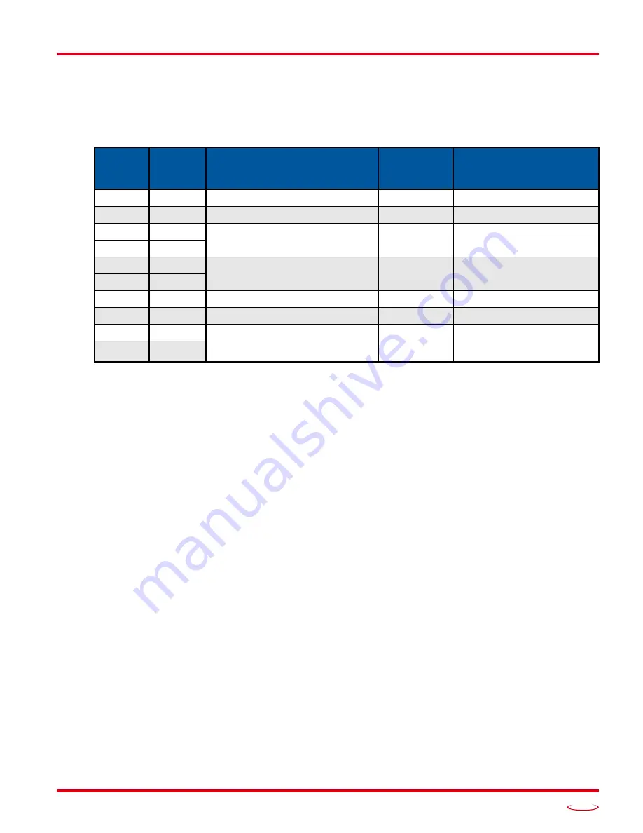
Table R6.10 Axis Follower Move Command Block
When the command is accepted, the value in words 8 and 9 determine the type of move. If the value equals
zero, the move is treated as a linear axis follower. If the value is between 1,024 and 1,073,741,824, the move
is treated as a circular axis follower. Once the move has begun, the type of follower move cannot be changed.
Once the command is accepted, the
Stopped
bit (Word 0, bit 3 in the Input Data), is reset to “0” and remains
zero as long as the axis follower command remains active. It will not be reset to zero if the position from the
master axis stops changing. Use the
Moving_CW
and
Moving_CCW
bits (Word 0, bits 0 and 1 in the Input
Data), to determine when motion from the SV160E2 is occurring.
When the command is accepted, the acceleration programmed in word 6 is used to accelerate to the present
speed of the move. Once this speed is achieved, the SV160E2 will use the value in word 6 to determine how
quickly it reacts to the changes in position from the master axis. (Once the SV160E2 initially accelerates to
the preset speed of the virtual axis, the unit accepts changes in the acceleration value in word 6 as part of the
virtual axis commands.)
Once the SV160E2 is following the axis, (the
Stopped
bit is reset to “0”), Word 8 can be used to program the
Maximum Move Torque. The
Motor_Torque
bit (Command Word 1, bit 1) must be set to “1” to program the
torque. The Maximum Move Torque must be in word 8 and word 9 must equal 0.
https://www.amci.com/industrial-automation-support/sample-programs/
. The Linear and Circu-
lar Add On Instructions available in the sample program, have all of the above parameters and automatically
place the values in the correct registers based on the state of the Stopped status bit.
If you are using a different host controller that supports motion axis programming, feel free to contact AMCI
technical support for assistance in programming your controller.
EtherNet/IP
or PROFINET
Word
Modbus TCP
Register
Function
Units
Range
0
1024
16#0080 or 16#0100
1
1025
16#1000
2
1026
32 bit Position Value
Steps
Range of -1,073,741,824
to +1,073,741,823
3
1027
4
1028
32 bit Programmed Speed
Steps/Second
Range of ±1,048,575
5
1029
6
1030
Acceleration
Steps/ms/sec
Range of ±15,999
7
1031
Deceleration
Steps/ms/sec
1 to 15,999
8
1032
32 bit Unwind Value
or
Maximum Move Torque
Steps
or
0.01 Nm
0, 1,024 to 1,073,741,824
or
0, 10 to 130
9
1033
Summary of Contents for SV160E2
Page 1: ...MICRO CONTROLS INC ADVANCED U s e r M anual Manual 940 0S252 E2 Technology...
Page 10: ...ABOUT THIS MANUAL SV160E2 User Manual ADVANCED MICRO CONTROLS INC 10 Notes...
Page 40: ...MOVE PROFILE CALCULATIONS SV160E2 User Manual ADVANCED MICRO CONTROLS INC 40 Notes...
Page 56: ...CONFIGURATION MODE DATA FORMAT SV160E2 User Manual ADVANCED MICRO CONTROLS INC 56 Notes...
Page 88: ...INSTALLING THE SV160E2 SV160E2 User Manual ADVANCED MICRO CONTROLS INC 88 Notes...
Page 108: ...ETHERNET IP EXPLICIT MESSAGING SV160E2 User Manual ADVANCED MICRO CONTROLS INC 108 Notes...
Page 112: ...MODBUS TCP CONFIGURATION SV160E2 User Manual ADVANCED MICRO CONTROLS INC 112 Notes...
Page 120: ...LEADERS IN ADVANCED CONTROL PRODUCTS ADVANCED MICRO CONTROLS INC...