


C
OMMAND
M
ODE
D
ATA
F
ORMAT
SV160E2 User Manual
ADVANCED MICRO CONTROLS INC.
70
Input Data Format (continued)
Status Word 0 Format (continued)
Bit 10: Position_Invalid –
“1” when:
An error is detected in the absolute encoder on power up
If the difference between the Profile Position and Encoder Position is greater than 4,096
counts when attempting to enable the motor.
If the difference between the Profile Position and Encoder Position exceeds the value of the
Maximum Position Error Limit after a stall is detected and the SV160E2 has come to a stop.
Bits 9 & 8: Reserved –
Will always equal “0”.
Bit 7: Move_Complete –
Set to “1” when the present Absolute, Relative, or Registration Move completes
without error. This bit is reset to “0” when the next move command is written to the SV160E2, when
the position is preset, or a Reset Errors command is issued to the unit. This bit is not set at the end of
a jog move or a homing operation.
Bit 6: Decelerating –
Set to “1” when the present move is decelerating. Set to “0” at all other times.
Bit 5: Accelerating –
Set to “1” when the present move is accelerating. Set to “0” at all other times.
Bit 4: At_Home –
Set to “1” when a homing command has completed successfully, “0” at all other times.
Bit 3: Stopped –
For normal moves, set to “1” when the motor is not in motion. Note that this is stopped
for any reason, not just a completed move. For example, an Immediate Stop command during a
move will set this bit to “1”, but the Move_Complete Bit, (bit 7 above) will not be set.
For Axis Follower Moves, the Stopped bit resets to “0” once the command is accepted and remains
reset until the Axis Follower Move ends. The Moving_CW and Moving_CCW bit can be used to
determine if motion is occurring during an Axis Follower Move.
Bit 2: In_Hold_State –
Set to “1” when a move command has been successfully brought into a Hold State.
Hold States are explained is the
Bit 1: Moving_CCW –
Set to “1” when the motor is rotating in a counter-clockwise direction.
Bit 0: Moving_CW –
Set to “1” when the motor is rotating in a clockwise direction.
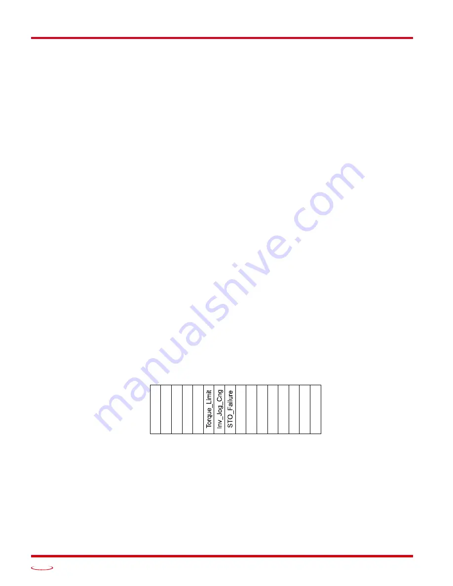
Status Word 1 Format
Figure R6.5 Command Mode: Status Word 1 Format
Bit 15: Drive_Is_Enabled –
Set to “1” when the motor driver section of the SV160E2 is enabled and current
is available to the motor. Set to “0” when the motor driver section is disabled. If this bit is set to “1”,
the motor current remains present when an E-Stop input is active.
Bit 14: Stall_Detected –
Set to “1” when the difference between the commanded motor position and the
encoder position exceeds the value of the Maximum Position Error Limit parameter. This parameter
is set in the
Block 6: Position Control Loop Configuration Block
Status Word 1
15 14 13 12 11 10 09 08 07 06 05 04 03 02 01 00
Dri
v
e
_
Enabl
ed
Sta
ll_
Det
e
ct
ed
Abs_
En
c_Er
r
Cm
d
_
Ack
T
e
m
p_90
°C
IN
3
_
A
c
tiv
e
IN
4
_
A
c
tiv
e
IN
2
_
A
c
tiv
e
IN
1
_
A
c
tiv
e
Dr
iv
er_F
aul
t
Conn
ec
t_L
o
st
STO
_
Act
iv
e
H
ear
tbea
t_Bi
t
Summary of Contents for SV160E2
Page 1: ...MICRO CONTROLS INC ADVANCED U s e r M anual Manual 940 0S252 E2 Technology...
Page 10: ...ABOUT THIS MANUAL SV160E2 User Manual ADVANCED MICRO CONTROLS INC 10 Notes...
Page 40: ...MOVE PROFILE CALCULATIONS SV160E2 User Manual ADVANCED MICRO CONTROLS INC 40 Notes...
Page 56: ...CONFIGURATION MODE DATA FORMAT SV160E2 User Manual ADVANCED MICRO CONTROLS INC 56 Notes...
Page 88: ...INSTALLING THE SV160E2 SV160E2 User Manual ADVANCED MICRO CONTROLS INC 88 Notes...
Page 108: ...ETHERNET IP EXPLICIT MESSAGING SV160E2 User Manual ADVANCED MICRO CONTROLS INC 108 Notes...
Page 112: ...MODBUS TCP CONFIGURATION SV160E2 User Manual ADVANCED MICRO CONTROLS INC 112 Notes...
Page 120: ...LEADERS IN ADVANCED CONTROL PRODUCTS ADVANCED MICRO CONTROLS INC...