SwitchBlade x8112 Chassis Switch and AT-SBx81CFC960 Card Installation Guide
Section I: Hardware Overview
43
LEDs
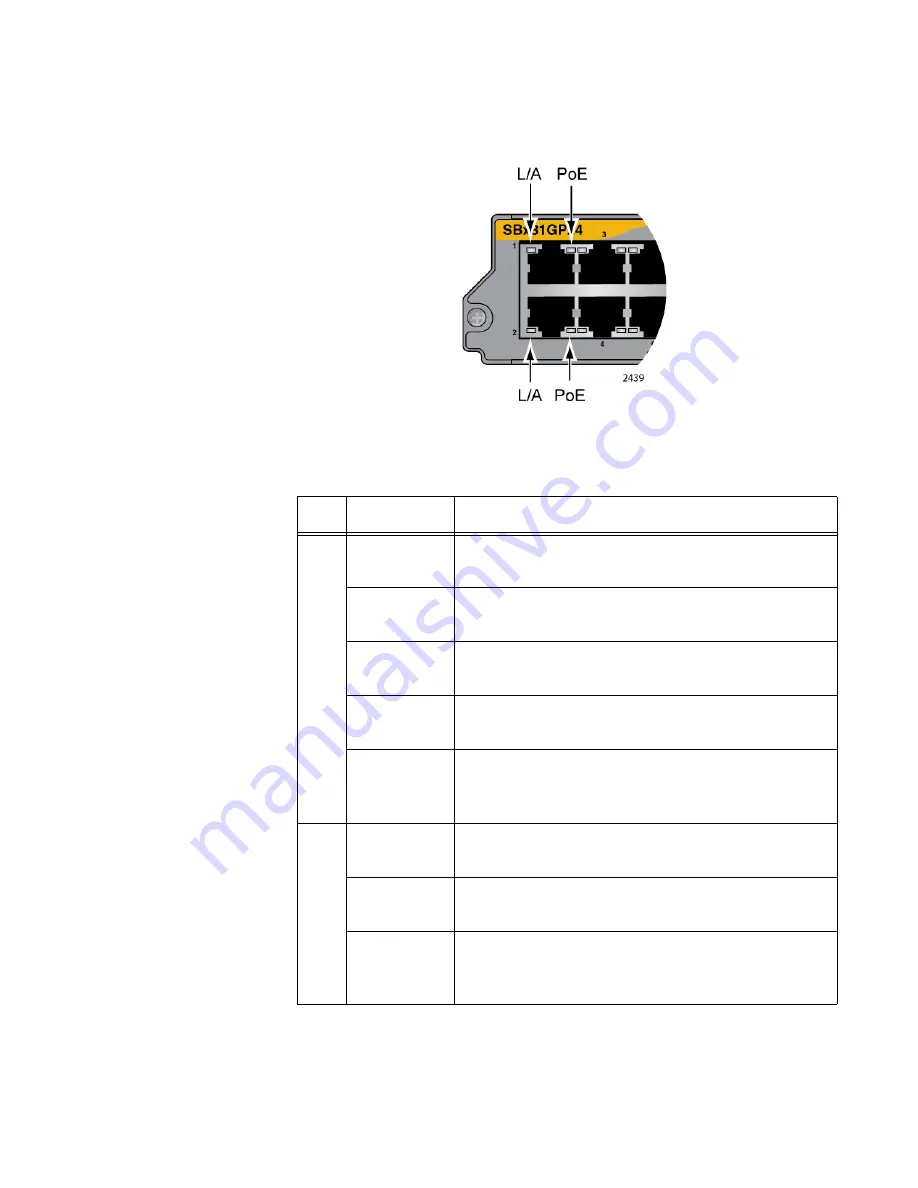
Each port on the AT-SBx81GP24 PoE Line Card has two LEDs. The LEDs
are shown in Figure 17 and described in Table 8.
Figure 17. Port LEDs on the AT-SBx81GP24 PoE Line Card
Table 8. Port LEDs on the AT-SBx81GP24 PoE Line Card
LED
State
Description
L/A
Solid Green
The port has established an 1000 Mbps link to a
network device.
Flashing
Green
The port is transmitting or receiving data at 1000
Mbps.
Solid Amber
The port has established a 10 or 100 Mbps link to
a network device.
Flashing
Amber
The port is transmitting or receiving data at 10 or
100 Mbps.
Off
The port has not established a link with another
network device or the LEDs are turned off. To turn
on the LEDs, use the eco-friendly button.
PoE
Green
The switch is detecting a powered device (PD) on
the port and is delivering power to it.
Solid Amber
The switch has shutdown PoE+ on the port
because of a fault condition.
Flashing
Amber
The switch is detecting a PD on the port but is not
delivering power to it because the maximum power
budget has been reached.
Summary of Contents for AT-SBx81CFC960
Page 14: ...List of Tables 14...
Page 20: ...20...
Page 34: ...Chapter 1 Chassis and Power Supplies 34 Section I Hardware Overview...
Page 80: ...80...
Page 104: ...Chapter 5 Installing the Chassis in an Equipment Rack 104 Section II Installing the Chassis...
Page 124: ...Chapter 6 Installing the Power Supplies 124 Section II Installing the Chassis...
Page 262: ...Chapter 12 Replacing Modules 262 Section II Installing the Chassis...
Page 270: ...Chapter 13 Upgrading the Controller Fabric Card 270 Section II Installing the Chassis...
Page 272: ...272...
Page 286: ...Chapter 14 VCStack Plus Overview 286 Section III Building a Stack with VCStack Plus...


