


FS2 Frame Synchronizer/Converter v3.0 108 www.aja.com
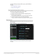
Figure 16. Typical GPI Input and Output Connections
1
15
11
5
6
10
GPI Out 4
GPI
In 1
+V
xmit+
xmit-
Optical Relay (SSR)
To Tally Lamp etc.
GPI GND 4
GPI
GND 1
The figure above shows typical external wiring to the GPI connector. The GPI
inputs require some kind of contact closure between the input pin and the input
ground pin to register the logic low that triggers the GPI input.
You can connect the outputs to TTL buffers that communicate the GPI output
logic levels to other devices. For example, you could use an opto-isolator
controlling a relay to activate other equipment as shown below.
Audio Connection Pinouts
Analog Audio
Figure 17. Audio Connector Pinout
G - +G - +G - +G - +G - +G - +G - +G - +
G = Ground
+/- = Balanced Pair
Key
The two DB25 connectors on the FS2 rear panel support a TASCAM-style cable
snake for balanced 8-channel analog audio. The pinout is the same for both input
and output connectors, each following the TASCAM DB-25 standard shown in the
drawing above. The top connector is for analog audio inputs 1-8, and the bottom
connector is for analog audio outputs 1-8
Digital Audio
The same pinout scheme as above is used for the AES/EBU digital audio
connections, except each channel handles a pair of digital audio signals (16 total
per connector). The top connector is for digital audio input channels 1-16, and the
bottom connector is for digital audio output channels 1-16.