33
12.
Attach the rudder servo coupler assembly to
the rudder servos as shown. Do not tighten the
easy link set screws until the rudder servos are
powered up and centered.
13.
Optional ball link rudder servo coupler assem-
bly is shown below. Use 4-40 ball links and
4-40 all thread with copper, brass, or carbon
tubes over the all thread rod to give adequate
strength.
Note
: Rudder coupler hardware is not supplied
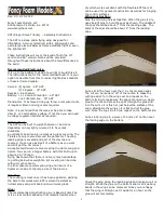
14.
Tape the rudder balance tab to the top leading
edge of the vertical fin in the neutral position
as shown. This ensures the rudder is straight
when the cables are attached.
15.
Screw threaded coupler halfway into ball link