2 Chassis Enclosure
20
To reset these values, press and hold the Reset button for five seconds.
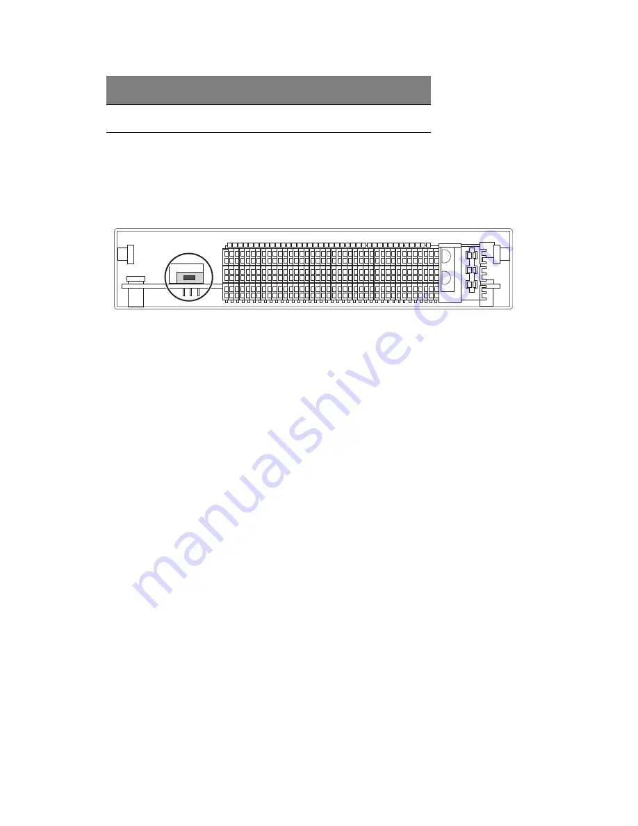
USB Switch
Figure 2-10. USB Switch on Rear of CMM
The USB ports on the CMM can function in either 2.0 or 1.1 mode (the
default is 1.1). A switch located on the PCB at the back of the CMM
module is used to change the USB mode (see Figure 2-10).
To access the switch, you need to remove the CMM from the enclosure.
Pull the CMM out and locate the switch near the large gray connector.
The settings are silk screened on the PCB. After setting the switch,
insert the CMM module back into its bay.
Module Installation
Make sure the cover to the module has been installed before
proceeding.
Installing the Module:
1. Remove the dummy cover from the bay you want to place the
module in.
2. Place the module's release handle in the open position.
3. Slide the module into the module bay until it stops.
4. Push the release handle to the closed position.
5. After the module has been installed and the handle locked, it will
turn on and a POST test will run to verify it is working properly.
Subnet Mask
Reset to 255.255.255.0
Software Setting
Default
Summary of Contents for AB460 F1
Page 1: ...AB7000 Series User Guide ...
Page 14: ...xiv ...
Page 21: ...1 Document Description ...
Page 24: ...1 Document Description 4 ...
Page 25: ...2 Chassis Enclosure ...
Page 37: ...17 Figure 2 8 Enclosure Installed into Rack ...
Page 111: ...3 Server Blades Setup and Installation ...
Page 121: ...101 Figure 3 60 Card Installation ...
Page 171: ...151 4 DIMMs system memory 5 Airflow Deflector 6 CPU Heatsinks 7 Top Cover Item Description ...
Page 280: ...3 Server Blades Setup and Installation 260 ...
Page 281: ...4 Networking Switch Modules ...
Page 573: ...5 Acer Smart Blade Manager ...
Page 600: ...5 Acer Smart Blade Manager 580 ...
Page 601: ...Appendix A Troubleshooting ...
Page 616: ...Appendix A Troubleshooting 596 ...


