


650997/032 M3349 - 1999/11/03 fr-en - Rev. 6-2002 - 41/56
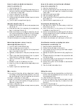
Fig. 20
Local d’installation
Le local d’installation doit être prédisposé sur la base des
dimensions et de la version du tableau. Le respect des cotes
indiquées garantit le bon fonctionnement de l’appareillage.
Pour tableaux dans la version avec tenue à l’arc interne prévoir,
dans le local d’installation, un système d’évacuation des
surpressions.
Installation room
The installation room must be prepared according to the dimen-
sions and version of the switchboard. Compliance with the
distances indicated ensures correct operation of the apparatus.
For internally arc proof switchboards, provide a space for the gas
exhaust duct in the installation room.
(1) Pour cellules P1E et P1E/2R, D = 1400 mm.
(1) For P1E e P1E/2R units, D = 1400 mm.
Tableau
A
B
C
Switchboard
[mm]
[mm]
[mm]
Standard
> 50
> 50
> 800 (1)
Arc interne
> 600
> 50
> 800 (1)
Internally arc-proof
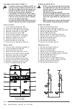
9.4. Fondations et plan de fixation
Le tableau est normalement prédisposé pour le raccordement
par le bas aussi bien du circuit de moyenne tension que des
circuits auxiliaires. L’utilisation du caisson (AC) permet la
réalisation de l’arrivée des câbles de MT par le haut.
Avant de procéder à l’installation du tableau, il est nécessaire
de préparer des trous de passage sous chaque cellule. Le
dessin de principe des fondations est reporté à la fig. 21.
Le tableau peut être fixé (fig. 22) directement au sol ou sur des
fers de base appropriés (pouvant être fournis sur demande).
• Pour la fixation directe utiliser des boulons à expansion en
correspondance des trous de fixation.
• Pour celle avec des fers de base sont prévus des blocs avec
boulons spéciaux. Les fers doivent être fixés et incorporés
dans la coulée de la semelle.
Dans tous les cas le plan de fixation doit être horizontal et bien
nivelé avec une tolérance de planéité de 2 x 1000.
Remarque: pour les fondations et la fixation du tableau sont prévus des
dessins spécifiques qui sont envoyés par ABB après l’émission de la
confirmation du bon de commande, afin de permettre la préparation du
lieu de l’installation.
9.4. Foundations and fixing surface
The switchboard is normally prepared for connection of both the
medium voltage circuit and the auxiliary circuits from below. The
use of the box (AC) allows incoming MV cables from above.
Before installation of the switchboard, special passage holes
under each cubicle must be prepared. The overall drawing of the
foundations is shown in fig. 21.
Switchboard fixing (fig. 22) can be carried out directly on the floor
or it can be placed on special base irons (supplied on request).
• For direct fixing to the floor, use expansion anchoring bolts in
correspondence with the fixing holes.
• For fixing with base irons, special blocks with bolts are
provided. The base irons must be fixed and embedded in the
concrete slab surface.
In any case, the fixing surface must be horizontal and well
levelled with a level tolerance of 2 x 1000.
Note: after issue of the order confirmation, special drawings are
promptly prepared and sent by ABB for the foundations and for fixing
the switchboard, to allow the installation site to be prepared.
Devant
Front
Devant
Front
Summary of Contents for UniAir
Page 2: ......
Page 40: ...38 56 650997 032 M3349 1999 11 03 fr en Rev 6 2002 Fig 18 ...
Page 59: ......


