


24/56 - 650997/032 M3349 - 1999/11/03 fr-en - Rev. 6-2002
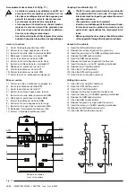
Cellule type P1E/2R (HAD) fig.11
• Si l’on effectue des manœuvres avec le disjonc-
teur extrait du tableau faire très attention aux
parties en mouvement.
• Le disjoncteur doit être embroché dans la cellule
seulement en position d’ouverture; l’introduction
et l’extraction doivent être graduels pour éviter
des chocs pouvant provoquer la déformation des
verrouillages mécaniques.
• Avant d’ouvrir le sectionneur de terre et fermer le
sectionneur de barre, s’assurer d’avoir raccordé
le connecteur du disjoncteur à la prise des auxiliai-
res du tableau.
• Avant d’ouvrir la porte vérifier toujours à travers les
hublots d’inspection la position des appareillages.
• En cas d’accouplement avec d’autres cellules,
ayant besoin pour des exigences d’installation des
verrouillages interagissant entre eux, le client
devra unir les clés par un anneau soudé de ma-
nière à assurer la sécurité de la séquence des
manœuvres.
• La procédure de mise en sécurité pour l’accessi-
bilité au logement de connexion de l’alimentation
est aux bons soins du client étant donné qu’elle
dépend du schéma électrique réalisé.
Accès à la cellule et extraction du disjoncteur
Accès à la cellule (fig. 11)
1)
Ouvrir le disjoncteur
2)
Enlever la clé(I) du verrouillage du disjoncteur et se servir
de la deuxième clé baguée (L) pour débloquer les section-
neurs de ligne
3)
Ouvrir les sectionneurs de ligne (L)
4)
Vérifier la position des parties mobiles à travers les hublots
d’inspection (3)
5)
Ouvrir la porte du compartiment disjoncteur (4).
Extraction disjoncteur (fig. 10)
6)
Débrancher le connecteur (3) des circuits auxiliaires de la
prise (4)
7)
Accrocher le chariot (1) à la structure (2) du compartiment
disjoncteur en actionnant le levier (7)
8)
Enlever la clé (L) du verrouillage du sectionneur de ligne
et se servir de la deuxième clé baguée (C) du verrouillage
embrochage/extraction du disjoncteur pour le débloquer
9)
Débloquer le disjoncteur en actionnant le levier (5)
10) Sortir le disjoncteur en le plaçant sur le chariot (1).
Embrochage disjoncteur et mise en service
Embrochage disjoncteur (fig. 10)
1)
Ouvrir la porte du compartiment disjoncteur
2)
Placer le disjoncteur sur le chariot (1)
3)
Accrocher le chariot (1) à la structure (2) du compartiment
disjoncteur en actionnant le levier (7)
4)
Débloquer le disjoncteur du chariot en actionnant le le-
vier(5)
5)
Insérer progressivement le disjoncteur dans le comparti-
ment jusqu’à son introduction complète
6)
Insérer le connecteur (3) des circuits auxiliaires dans la
prise (4)
7)
Actionner le levier (7) et débloquer le chariot (1)
8)
Enlever la clé du verrouillage embrochage/extraction dis-
joncteur (C)
9)
Fermer la porte du compartiment disjoncteur.
!
!
P1E/2R (HAD) type unit (fig. 11)
• Should any operations be carried out with the
circuit-breaker withdrawn from the switchboard,
pay maximum attention to moving parts.
• The circuit-breaker must only be connected in the
unit in the open position. Connection and with-
drawal must be gradual to prevent any impacts
which might deform the mechanical interlocks.
• Before opening the earthing switch and closing the
busbar isolator, make sure that the circuit-breaker
connector has been connected to the socket of the
switchboard auxiliaries.
• Before opening the door, always check the position
of the apparatus through the inspection windows.
• In the case of coupling with other units, which,
because of installation requirements, need inter-
locks which interact, the customer must join the
keys together with a welded ring to guarantee
safety of the operation sequence.
• The procedure for gaining safe access to the cable
housing where the power supply is headed must be
carried out by the customer since it depends on the
type of electrical circuit constructed.
Access to the cubicle and circuit-breaker withdrawal
Access to the cubicle (fig. 11)
1) Open the circuit-breaker
2) Remove the key (I) from the circuit-breaker lock and use the
second ringed key (L) to release the line-side isolators
3) Open the line-side isolators (L)
4) Check the position of the moving parts through the inspec-
tion windows (3)
5) Open the circuit-breaker compartment door (4).
Circuit-breaker withdrawal (fig. 10)
6) Disconnect the connector (3) of the auxiliary circuits from the
socket (4)
7) Hook up the truck (1) to the structure (2) of the circuit-breaker
compartment, using the lever (7)
8) Remove the key (L) from the line-side isolator lock and use
the second ringed key (C) of the circuit-breaker connection/
withdrawal lock to release it
9) Release the circuit-breaker by using the lever (5)
10)Slide the circuit-breaker out, positioning it on the truck (1).
Circuit-breaker connection and putting into service
Circuit-breaker connection (fig. 10)
1) Open the circuit-breaker compartment door
2) Position the circuit-breaker on the truck (1)
3) Hook the truck up tot he structure (2) of the circuit-breaker
compartment using the lever (7)
4) Release the circuit-breaker from the truck by using the lever
(5)
5) Gradually insert the circuit-breaker in the compartment until
it is fully connected
6) Connect the auxiliary circuit connector (3) in the socket (4)
7) Use the lever (7) and release the truck (1)
8) Remove the key from the circuit-breaker connection/with-
drawal lock (C)
9) Close the circuit-breaker compartment door.
Summary of Contents for UniAir
Page 2: ......
Page 40: ...38 56 650997 032 M3349 1999 11 03 fr en Rev 6 2002 Fig 18 ...
Page 59: ......


