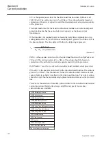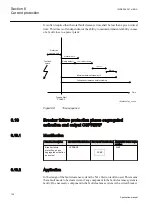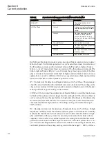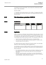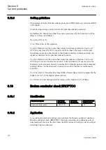
SN>
is the operate power level for the directional function when
OpMode
is set
3I03U0Cosfi
. The setting is given in % of
SBase
. The setting should be based on
calculation of the active or capacitive earth-fault residual power at required sensitivity
of the protection.
The input transformer for the Sensitive directional residual over current and power
protection function has the same short circuit capacity as the phase current
transformers.
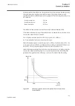
If the time delay for residual power is chosen the delay time is dependent on two
setting parameters.
SRef
is the reference residual power, given in % of
SBase
.
kSN
is
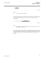
the time multiplier. The time delay will follow the following expression:
inv
0
0
kSN Sref
t
3I 3U cos (measured)
j
×
=
×
×
EQUATION1957 V1 EN
(Equation 42)
INDir>
is the operate current level for the directional function when
OpMode
is set
3I0 and fi
. The setting is given in % of
IBase
. The setting should be based on
calculation of the earth-fault current at required sensitivity of the protection.
OpINNonDir>
is set
On
to activate the non-directional residual current protection.
INNonDir>
is the operate current level for the non-directional function. The setting is
given in % of
IBase
. This function can be used for detection and clearance of cross-
country faults in a shorter time than for the directional function. The current setting
should be larger than the maximum single-phase residual current out on the protected
line.
TimeChar
is the selection of time delay characteristic for the non-directional residual
current protection. Definite time delay and different types of inverse time
characteristics are available:
ANSI Extremely Inverse
ANSI Very Inverse
ANSI Normal Inverse
ANSI Moderately Inverse
ANSI/IEEE Definite time
ANSI Long Time Extremely Inverse
ANSI Long Time Very Inverse
ANSI Long Time Inverse
IEC Normal Inverse
IEC Very Inverse
IEC Inverse
IEC Extremely Inverse
IEC Short Time Inverse
Table continues on next page
Section 6
1MRK 505 291-UEN A
Current protection
130
Application manual
Summary of Contents for Relion REQ650
Page 1: ...Relion 650 series Breaker protection REQ650 Application manual ...
Page 2: ......
Page 20: ...14 ...
Page 26: ...20 ...
Page 48: ...42 ...
Page 82: ...76 ...
Page 90: ...84 ...
Page 160: ...154 ...
Page 178: ...172 ...
Page 264: ...258 ...
Page 288: ...282 ...
Page 302: ...296 ...
Page 330: ...324 ...
Page 338: ...332 ...
Page 339: ...333 ...


